Heater & Air Conditioning Control System Type 3

Component parts

In this manual: Heater & Air Conditioning Control System Type 3
Foreword — 1General information — 45Engine Mechanical MR16DDT — 61Engine Mechanical HR16DE — 52Engine Mechanical K9K — 46Engine Lubrication System MR16DDT — 18Engine Lubrication System HR16DE — 14Engine Lubrication System K9K — 11Engine Cooling System MR16DDT — 28Engine Cooling System HR16DE — 29Engine Cooling System K9K — 24Engine Control System MR16DDT — 163Engine Control System HR16DE — 115Engine Control System K9K — 129Fuel System MR16DDT — 13Fuel system HR16DE — 11Fuel system K9K — 12Exhaust system MR16DDT — 7Exhaust system HR16DE — 10Exhaust system K9K — 7Starting system — 24Accelerator control system — 6Clutch — 25Driveline transfer: TY21B — 77Driveline rear propeller Shaft: 3Fφ16-ETJ75 — 12Driveline rear final drive: RTVS — 31Transaxle & transmission 5MT: RS5F92R — 31Transaxle & transmission 6MT: RS6F94R — 30Transaxle & transmission CVT: RE0F10B — 93Transaxle & transmissioN CVT: RE0F11A — 103Front Axle MR16DDT — 18Front Axle HR16DE — 17Front Axle K9K — 17Rear Axle 2WD — 6Rear Axle 4WD — 13Front Suspension — 21Rear Suspension 2WD — 13Rear Suspension 4WD — 17Road Wheels & Tires — 6Brake System LHD — 24Brake System RHD — 24Parking Brake System — 8Brake Control System without ESP — 44Brake Control System with ESP — 63Steering System — 14Steering Control System — 27Seat Belt — 8SRS Airbag — 24SRS Airbag Control System — 93Ventilation System — 11Heater & Air Conditioning System HR16DE — 28Heater & Air Conditioning System MR16DDT — 28Heater & Air Conditioning Control System Type 1 — 49Heater & Air Conditioning Control System Type 2 — 51Heater & Air Conditioning Control System Type 3 — 32Heater & Air Conditioning Control System Type 4 — 40Heater & Air Conditioning Control System Type 5 — 21Interior — 16Instrument Panel — 10Seat — 18Door & Lock Type 1 — 83Door & Lock type 2 — 80Door & Lock type 3 — 65Door & Lock type 4 — 60Security Control System with intelligent key system — 82Security Control System without intelligent key system — 41Glass & Window System — 15Power Window Control System — 28Body Repair — 13Exterior — 20Mirrors — 26Exterior Lighting System Halogen type — 51Interior Lighting System — 24Wiper & Washer — 45Defogger — 31Horn — 4Power Outlet — 4Body Control System With intelligent key system — 21Body Control System Without intelligent key system — 23LAN system can fundamental — 6LAN system can — 31LAN System can system (type 1) — 1LAN System can system (type 2) — 1LAN System can system (type 3) — 1LAN System can system (type 4) — 1LAN System can system (type 5) — 1LAN System can system (type 6) — 1LAN System can system (type 7) — 2LAN System can system (type 8) — 1LAN System can system (type 9) — 1LAN System can system (type 10) — 1LAN System can system (type 11) — 1Power Control System IPDM E/R (with I-key) — 14Power Control System IPDM E/R (without I-key) — 14Power Control System Power distribution system — 25Charging System — 22Power Supply, Ground & Circuit Elements — 20Meter, Warning Lamp & Indicator — 33Warning Chime System — 22Audio, Visual & Navigation System Audio without navigation — 30Audio, Visual & Navigation System Audio with navigation — 33Audio, Visual & Navigation System NISSAN dynamic control system — 22Cruise Control System — 1Drive Mode System — 10Maintenance — 14
~3min read

Component Part Location

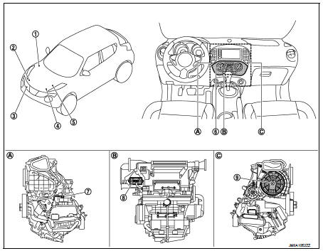
1. BCM

1. BCM
• With Intelligent Key: Refer to BCS- 6, "BODY CONTROL SYSTEM : Component Parts Location". • Without Intelligent Key: Refer to BCS-96, "BODY CONTROL SYSTEM : Component Parts Location". 2. Magnet clutch
3. Refrigerant pressure sensor 4. ECM Refer to EC-25, "ENGINE CONTROL SYSTEM : Component Parts Location". 5. IPDM E/R
• With Intelligent Key: Refer to PCS- 5, "Component Parts Location". • Without Intelligent Key: Refer to PCS-37, "Component Parts Location".

6. A/C control
7. Thermo control amp.
8. Blower fan resistor
9. Blower motor

A. Left side of A/C unit assembly B. Back side of A/C unit assembly C. Right side of A/C unit assembly

Component Description
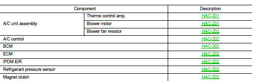
A/C unit assembly : Thermo Control Amp.

A/C unit assembly : Thermo Control Amp.

• Thermo control amp. is composed of thermistor and amplifier. Thermistor is installed on evaporator, and amplifier is attached to foot duct.

• When the thermistor detecting temperature of the evaporator fin is extremely low, thermo control amp. sends the thermo control amp. OFF signal to BCM, and stops the compressor.

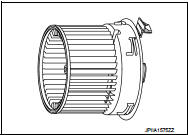
A/C unit assembly : Blower Motor

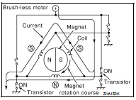
• The blower motor utilizes a brush-less motor with a rotating magnet.

• Quietness is improved over previous motors where the brush was the point of contact and the coil rotated.
A/C unit assembly : Blower Fan Resistor

A/C unit assembly : Blower Fan Resistor

• Compact and lightweight resistor is adopted with outstanding ventilation.

• Temperature fuse is installed to protects the blower motor circuit.
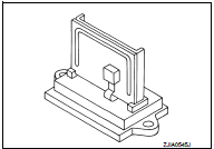
A/C Control

A/C Control

Controls the air conditioning function.

BCM

BCM transmits A/C ON signal and blower fan ON signal to ECM via CAN communication, according to A/C switch signal and blower fan ON signal that are received from A/C control and thermo control amp. signal that is received from thermo control amp. and A/C indicator is turned ON.

ECM

ECM, when receiving A/C ON signal and blower fan ON signal from BCM, transmits A/C compressor request signal to IPDM E/R via CAN communication according to status of the engine and refrigerant pressure.

IPDM E/R

A/C relay is integrated in IPDM E/R. IPDM E/R operates A/C relay when A/C compressor request signal is received from ECM via CAN communication line.

Refrigerant Pressure Sensor

DESCRIPTION

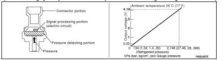
• The refrigerant pressure sensor converts high-pressure side refrigerant pressure into voltage and outputs it to ECM.

• ECM operates cooling system protection and idle speed control according to voltage value that is input.
STRUCTURE AND OPERATION

STRUCTURE AND OPERATION

• The refrigerant pressure sensor is a capacitance type sensor. It consists of a pressure detection ares and a signal processing area. • The pressure detection area, which is a variable capacity condenser, changes internal static capacitance according to pressure force.

• The signal processing area detects the static capacitance of the pressure detection area, converts the static capacitance into a voltage value, and transmits the voltage value to ECM.

Magnet Clutch

Compressor is driven by the magnet clutch which is magnetized by electric power supply.