Heater & Air Conditioning Control System Type 3

System

In this manual: Heater & Air Conditioning Control System Type 3
Foreword — 1General information — 45Engine Mechanical MR16DDT — 61Engine Mechanical HR16DE — 52Engine Mechanical K9K — 46Engine Lubrication System MR16DDT — 18Engine Lubrication System HR16DE — 14Engine Lubrication System K9K — 11Engine Cooling System MR16DDT — 28Engine Cooling System HR16DE — 29Engine Cooling System K9K — 24Engine Control System MR16DDT — 163Engine Control System HR16DE — 115Engine Control System K9K — 129Fuel System MR16DDT — 13Fuel system HR16DE — 11Fuel system K9K — 12Exhaust system MR16DDT — 7Exhaust system HR16DE — 10Exhaust system K9K — 7Starting system — 24Accelerator control system — 6Clutch — 25Driveline transfer: TY21B — 77Driveline rear propeller Shaft: 3Fφ16-ETJ75 — 12Driveline rear final drive: RTVS — 31Transaxle & transmission 5MT: RS5F92R — 31Transaxle & transmission 6MT: RS6F94R — 30Transaxle & transmission CVT: RE0F10B — 93Transaxle & transmissioN CVT: RE0F11A — 103Front Axle MR16DDT — 18Front Axle HR16DE — 17Front Axle K9K — 17Rear Axle 2WD — 6Rear Axle 4WD — 13Front Suspension — 21Rear Suspension 2WD — 13Rear Suspension 4WD — 17Road Wheels & Tires — 6Brake System LHD — 24Brake System RHD — 24Parking Brake System — 8Brake Control System without ESP — 44Brake Control System with ESP — 63Steering System — 14Steering Control System — 27Seat Belt — 8SRS Airbag — 24SRS Airbag Control System — 93Ventilation System — 11Heater & Air Conditioning System HR16DE — 28Heater & Air Conditioning System MR16DDT — 28Heater & Air Conditioning Control System Type 1 — 49Heater & Air Conditioning Control System Type 2 — 51Heater & Air Conditioning Control System Type 3 — 32Heater & Air Conditioning Control System Type 4 — 40Heater & Air Conditioning Control System Type 5 — 21Interior — 16Instrument Panel — 10Seat — 18Door & Lock Type 1 — 83Door & Lock type 2 — 80Door & Lock type 3 — 65Door & Lock type 4 — 60Security Control System with intelligent key system — 82Security Control System without intelligent key system — 41Glass & Window System — 15Power Window Control System — 28Body Repair — 13Exterior — 20Mirrors — 26Exterior Lighting System Halogen type — 51Interior Lighting System — 24Wiper & Washer — 45Defogger — 31Horn — 4Power Outlet — 4Body Control System With intelligent key system — 21Body Control System Without intelligent key system — 23LAN system can fundamental — 6LAN system can — 31LAN System can system (type 1) — 1LAN System can system (type 2) — 1LAN System can system (type 3) — 1LAN System can system (type 4) — 1LAN System can system (type 5) — 1LAN System can system (type 6) — 1LAN System can system (type 7) — 2LAN System can system (type 8) — 1LAN System can system (type 9) — 1LAN System can system (type 10) — 1LAN System can system (type 11) — 1Power Control System IPDM E/R (with I-key) — 14Power Control System IPDM E/R (without I-key) — 14Power Control System Power distribution system — 25Charging System — 22Power Supply, Ground & Circuit Elements — 20Meter, Warning Lamp & Indicator — 33Warning Chime System — 22Audio, Visual & Navigation System Audio without navigation — 30Audio, Visual & Navigation System Audio with navigation — 33Audio, Visual & Navigation System NISSAN dynamic control system — 22Cruise Control System — 1Drive Mode System — 10Maintenance — 14
~3min read

System Diagram

System Description

System Description

DESCRIPTION

• Manual air conditioning system is controlled by each function of thermo control amp., BCM, ECM and IPDM E/R.

• Fan speed of blower motor is changed by the combination of fan control dial operation and blower fan resistor control.

CONTROL BY THERMO CONTROL AMP.

HAC-203, "Compressor Control"

CONTROL BY BCM

HAC-203, "Compressor Control"

CONTROL BY ECM

• HAC-203, "Compressor Control" • Cooling fan control: Refer to EC-61, "COOLING FAN CONTROL : System Description".

CONTROL BY IPDM E/R
• HAC-203, "Compressor Control" • Cooling fan control

- With Intelligent Key system: Refer to PCS-9, "POWER CONTROL SYSTEM : System Description".

- Without Intelligent Key system: Refer to PCS-41, "POWER CONTROL SYSTEM : System Description"

Compressor Control

DESCRIPTION

• BCM transmits the A/C ON signal and blower fan ON signal to ECM via CAN communication line only when the compressor operational condition is satisfied, and A/C indicator is turned ON.

Refer to BCS-13, "SIGNAL BUFFER SYSTEM : System Description" (with Intelligent Key system) or BCS- 103, "SIGNAL BUFFER SYSTEM : System Description" (without Intelligent Key system).

NOTE:
Compressor operational condition • A/C switch signal: ON
• Blower fan ON signal: ON • Thermo control amp. signal: ON • ECM judges the conditions of each sensor (Refrigerant pressure sensor signal, accelerator position signal, etc.), and transmits the A/C compressor request signal to IPDM E/R via CAN communication line.

• By receiving the A/C compressor request signal from ECM, IPDM E/R turns the A/C relay to ON, and activates the compressor.

Refer to PCS-6, "RELAY CONTROL SYSTEM : System Description" (with Intelligent Key system) or PCS- 38, "RELAY CONTROL SYSTEM : System Description" (without Intelligent Key system).

CONTROL BY THERMO CONTROL AMP.

Low Temperature Protection Control • When the thermo control amp. detects that evaporator fin temperature is 2 °C or less, thermo control amp. signal becomes OFF, and stops the compressor.

• When the air temperature returns to 3,5 °C or more, the compressor is activated.

CONTROL BY ECM

CONTROL BY ECM

Compressor Protection Control at Pressure Malfunction The high-pressure side value that is detected by refrigerant pressure sensor is as per the following state, ECM requests IPDM E/R to turn A/C relay OFF and stop the compressor.

• 3.12 MPa (31.82 kg/cm2, 452.4 psi) or more (When the engine speed is less than 1,500 rpm)
• 2.74 MPa (27.95 kg/cm2, 397.3 psi) or more (When the engine speed is 1,500 rpm or more)
• 0.14 MPa (1.43 kg/cm2, 20.3 psi) or less

Compressor Oil Circulation Control When the engine starts while the engine coolant temperature is 56 °C or less, ECM activates the compressor for approximately 6 seconds and circulates the compressor oil once.

Air Conditioning Cut Control When the engine condition is high load, ECM makes the A/C relay to OFF, and stops the compressor.

Refer to EC-60, "AIR CONDITIONING CUT CONTROL : System Description".

Door Control

SWITCHES AND THEIR CONTROL FUNCTIONS

1. Intake door

1. Intake door
2. Blower motor
3. Air conditioner filter 4. Evaporator
5. Upper air mix door
6. Lower air mix door
7. Heater core
8. Foot door
9. Side ventilator door
10. Sub defroster door
11. Center ventilator and defroster door

Recirculation airFresh air intake
DefrosterRecirculation air
Center ventilatorDefroster
Side ventilatorCenter ventilator
FootSide ventilator
Rear foot*Foot
*: With rear foot ductRear foot*


*: With rear foot duct

AIR DISTRIBUTION

AIR DISTRIBUTION

Without rear foot duct
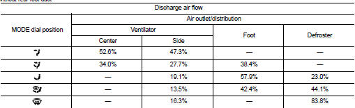
With rear foot duct

With rear foot duct

Operation