Engine Mechanical HR16DE

Compression pressure

In this manual: Engine Mechanical HR16DE
Foreword — 1General information — 45Engine Mechanical MR16DDT — 61Engine Mechanical HR16DE — 52Engine Mechanical K9K — 46Engine Lubrication System MR16DDT — 18Engine Lubrication System HR16DE — 14Engine Lubrication System K9K — 11Engine Cooling System MR16DDT — 28Engine Cooling System HR16DE — 29Engine Cooling System K9K — 24Engine Control System MR16DDT — 163Engine Control System HR16DE — 115Engine Control System K9K — 129Fuel System MR16DDT — 13Fuel system HR16DE — 11Fuel system K9K — 12Exhaust system MR16DDT — 7Exhaust system HR16DE — 10Exhaust system K9K — 7Starting system — 24Accelerator control system — 6Clutch — 25Driveline transfer: TY21B — 77Driveline rear propeller Shaft: 3Fφ16-ETJ75 — 12Driveline rear final drive: RTVS — 31Transaxle & transmission 5MT: RS5F92R — 31Transaxle & transmission 6MT: RS6F94R — 30Transaxle & transmission CVT: RE0F10B — 93Transaxle & transmissioN CVT: RE0F11A — 103Front Axle MR16DDT — 18Front Axle HR16DE — 17Front Axle K9K — 17Rear Axle 2WD — 6Rear Axle 4WD — 13Front Suspension — 21Rear Suspension 2WD — 13Rear Suspension 4WD — 17Road Wheels & Tires — 6Brake System LHD — 24Brake System RHD — 24Parking Brake System — 8Brake Control System without ESP — 44Brake Control System with ESP — 63Steering System — 14Steering Control System — 27Seat Belt — 8SRS Airbag — 24SRS Airbag Control System — 93Ventilation System — 11Heater & Air Conditioning System HR16DE — 28Heater & Air Conditioning System MR16DDT — 28Heater & Air Conditioning Control System Type 1 — 49Heater & Air Conditioning Control System Type 2 — 51Heater & Air Conditioning Control System Type 3 — 32Heater & Air Conditioning Control System Type 4 — 40Heater & Air Conditioning Control System Type 5 — 21Interior — 16Instrument Panel — 10Seat — 18Door & Lock Type 1 — 83Door & Lock type 2 — 80Door & Lock type 3 — 65Door & Lock type 4 — 60Security Control System with intelligent key system — 82Security Control System without intelligent key system — 41Glass & Window System — 15Power Window Control System — 28Body Repair — 13Exterior — 20Mirrors — 26Exterior Lighting System Halogen type — 51Interior Lighting System — 24Wiper & Washer — 45Defogger — 31Horn — 4Power Outlet — 4Body Control System With intelligent key system — 21Body Control System Without intelligent key system — 23LAN system can fundamental — 6LAN system can — 31LAN System can system (type 1) — 1LAN System can system (type 2) — 1LAN System can system (type 3) — 1LAN System can system (type 4) — 1LAN System can system (type 5) — 1LAN System can system (type 6) — 1LAN System can system (type 7) — 2LAN System can system (type 8) — 1LAN System can system (type 9) — 1LAN System can system (type 10) — 1LAN System can system (type 11) — 1Power Control System IPDM E/R (with I-key) — 14Power Control System IPDM E/R (without I-key) — 14Power Control System Power distribution system — 25Charging System — 22Power Supply, Ground & Circuit Elements — 20Meter, Warning Lamp & Indicator — 33Warning Chime System — 22Audio, Visual & Navigation System Audio without navigation — 30Audio, Visual & Navigation System Audio with navigation — 33Audio, Visual & Navigation System NISSAN dynamic control system — 22Cruise Control System — 1Drive Mode System — 10Maintenance — 14
~2min read
Inspection 1. Warm up engine thoroughly. Then, stop it. 2. Release fuel pressure. Refer to EC-551, "Work Procedure". 3. Remove ignition coil and spark plug from each cylinder. Refer to EM-178, "Exploded View". 4. Connect engine tachometer (not required in use of CONSULT-III).

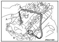
5. Install compression gauge (B) with an adapter (A) (commercial service tool) onto spark plug hole.
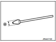
• Use the adapter whose picking up end inserted to spark plug

• Use the adapter whose picking up end inserted to spark plug hole is smaller than 20 mm (0.79 in) in diameter. Otherwise, it may be caught by cylinder head during removal.

a : 20 mm (0.79 in)
6. With accelerator pedal fully depressed, turn ignition switch to “START”

6. With accelerator pedal fully depressed, turn ignition switch to “START” for cranking. When the gauge pointer stabilizes, read the compression pressure and the engine rpm. Perform these steps to check each cylinder.

Compression pressure : Refer to EM-250, "General Specification".

CAUTION:
Always use a fully charged battery to obtain the specified engine speed.
• If the engine speed is out of the specified range, check battery liquid for proper gravity. Check the engine speed again with normal battery gravity. Refer to PG-111, "How to Handle Battery". • If compression pressure is below minimum value, check valve clearances, and parts associated with combustion chamber (valve, valve seat, piston, piston ring, cylinder bore, cylinder head, and cylinder head gasket). After the checking, measure compression pressure again.

• If some cylinder has low compression pressure, pour small amount of engine oil into the spark plug hole of the cylinder to recheck it for compression.

- If the added engine oil improves the compression, piston rings may be worn out or damaged. Check piston rings and replace if necessary.

- If the compression pressure remains at low level despite the addition of engine oil, valves may be malfunctioning.

Check valves for damage. Replace valve or valve seat accordingly.

• If two adjacent cylinders have respectively low compression pressure and their compression remains low even after the addition of engine oil, cylinder head gaskets are leaking. In such a case, replace cylinder head gaskets.

7. After inspection is completed, install removed parts. 8. Start the engine, and check that the engine runs smoothly.

9. Perform trouble diagnosis. If DTC appears, erase it. Refer to EC-558, "Description".