Engine Mechanical HR16DE

Camshaft valve clearance

In this manual: Engine Mechanical HR16DE
Foreword — 1General information — 45Engine Mechanical MR16DDT — 61Engine Mechanical HR16DE — 52Engine Mechanical K9K — 46Engine Lubrication System MR16DDT — 18Engine Lubrication System HR16DE — 14Engine Lubrication System K9K — 11Engine Cooling System MR16DDT — 28Engine Cooling System HR16DE — 29Engine Cooling System K9K — 24Engine Control System MR16DDT — 163Engine Control System HR16DE — 115Engine Control System K9K — 129Fuel System MR16DDT — 13Fuel system HR16DE — 11Fuel system K9K — 12Exhaust system MR16DDT — 7Exhaust system HR16DE — 10Exhaust system K9K — 7Starting system — 24Accelerator control system — 6Clutch — 25Driveline transfer: TY21B — 77Driveline rear propeller Shaft: 3Fφ16-ETJ75 — 12Driveline rear final drive: RTVS — 31Transaxle & transmission 5MT: RS5F92R — 31Transaxle & transmission 6MT: RS6F94R — 30Transaxle & transmission CVT: RE0F10B — 93Transaxle & transmissioN CVT: RE0F11A — 103Front Axle MR16DDT — 18Front Axle HR16DE — 17Front Axle K9K — 17Rear Axle 2WD — 6Rear Axle 4WD — 13Front Suspension — 21Rear Suspension 2WD — 13Rear Suspension 4WD — 17Road Wheels & Tires — 6Brake System LHD — 24Brake System RHD — 24Parking Brake System — 8Brake Control System without ESP — 44Brake Control System with ESP — 63Steering System — 14Steering Control System — 27Seat Belt — 8SRS Airbag — 24SRS Airbag Control System — 93Ventilation System — 11Heater & Air Conditioning System HR16DE — 28Heater & Air Conditioning System MR16DDT — 28Heater & Air Conditioning Control System Type 1 — 49Heater & Air Conditioning Control System Type 2 — 51Heater & Air Conditioning Control System Type 3 — 32Heater & Air Conditioning Control System Type 4 — 40Heater & Air Conditioning Control System Type 5 — 21Interior — 16Instrument Panel — 10Seat — 18Door & Lock Type 1 — 83Door & Lock type 2 — 80Door & Lock type 3 — 65Door & Lock type 4 — 60Security Control System with intelligent key system — 82Security Control System without intelligent key system — 41Glass & Window System — 15Power Window Control System — 28Body Repair — 13Exterior — 20Mirrors — 26Exterior Lighting System Halogen type — 51Interior Lighting System — 24Wiper & Washer — 45Defogger — 31Horn — 4Power Outlet — 4Body Control System With intelligent key system — 21Body Control System Without intelligent key system — 23LAN system can fundamental — 6LAN system can — 31LAN System can system (type 1) — 1LAN System can system (type 2) — 1LAN System can system (type 3) — 1LAN System can system (type 4) — 1LAN System can system (type 5) — 1LAN System can system (type 6) — 1LAN System can system (type 7) — 2LAN System can system (type 8) — 1LAN System can system (type 9) — 1LAN System can system (type 10) — 1LAN System can system (type 11) — 1Power Control System IPDM E/R (with I-key) — 14Power Control System IPDM E/R (without I-key) — 14Power Control System Power distribution system — 25Charging System — 22Power Supply, Ground & Circuit Elements — 20Meter, Warning Lamp & Indicator — 33Warning Chime System — 22Audio, Visual & Navigation System Audio without navigation — 30Audio, Visual & Navigation System Audio with navigation — 33Audio, Visual & Navigation System NISSAN dynamic control system — 22Cruise Control System — 1Drive Mode System — 10Maintenance — 14
~3min read
Inspection and Adjustment

INSPECTION

Perform inspection as follows after removal, installation or replacement of camshaft or valve-related parts, or if there is unusual engine conditions regarding valve clearance.

1. Remove rocker cover. Refer to EM-178, "Removal and Installation".

2. Measure the valve clearance with the following procedure: a. Set No. 1 cylinder at TDC of its compression stroke.

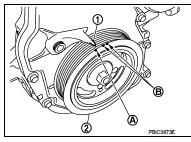
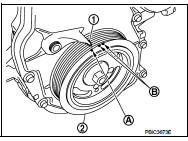
• Rotate crankshaft pulley (2) clockwise and align TDC mark (no paint) (A) to timing indicator (1) on front cover.

B : White paint mark (Not use for service)
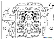
• At the same time, check that both intake and exhaust cam

• At the same time, check that both intake and exhaust cam noses of No. 1 cylinder face inside () as shown in the figure.
) as shown in the figure.

1 : Camshaft (INT)
2 : Camshaft (EXH)
• If they do not face inside, rotate crankshaft pulley once more: Engine front


• If they do not face inside, rotate crankshaft pulley once more (360 degrees) and align as shown in the figure.
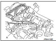
b. Use a feeler gauge (A), measure the clearance between valve

b. Use a feeler gauge (A), measure the clearance between valve lifter and camshaft.

Valve clearance : Refer to EM-251, "Camshaft".
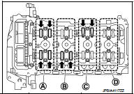
• By referring to the figure, measure the valve clearances at

• By referring to the figure, measure the valve clearances at locations marked “×” as shown in the table below [locations indicated with black arrow (the figure] with a feeler ) in
the figure] with a feeler gauge.


c. Set No. 4 cylinder at TDC of its compression stroke.

c. Set No. 4 cylinder at TDC of its compression stroke.

• Rotate crankshaft pulley (2) one revolution (360 degrees) and align TDC mark (no paint) (A) to timing indicator (1) on front cover.

B : White paint mark (Not use for service)
• By referring to the figure, measure the valve clearance at locations

• By referring to the figure, measure the valve clearance at locations marked “×” as shown in the table below [locations indicated with black arrow (with a feeler gauge. ) in the figure]
with a feeler gauge.


3. If out of standard, perform adjustment. Refer to “ADJUSTMENT”.

3. If out of standard, perform adjustment. Refer to “ADJUSTMENT”.

ADJUSTMENT

• Perform adjustment depending on selected head thickness of valve lifter.

1. Remove camshaft. Refer to EM-191, "Exploded View". 2. Remove valve lifters at the locations that are out of the standard.

3. Measure the center thickness of the removed valve lifters with a micrometer (A).
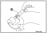
4. Use the equation below to calculate valve lifter thickness for

4. Use the equation below to calculate valve lifter thickness for replacement.

Valve lifter thickness calculation: t = t1 + (C1 – C2) t = Valve lifter thickness to be replaced t1 = Removed valve lifter thickness C1 = Measured valve clearance C2 = Standard valve clearance: Intake : 0.30 mm (0.012 in) Exhaust : 0.33 mm (0.013 in)

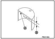
• Thickness of new valve lifter (B) can be identified by stamp mark (A) on the reverse side (inside the cylinder).

• Stamp mark “302” indicates 3.02 mm (0.1189 in) in thickness.
NOTE:

NOTE

:
Available thickness of valve lifter: 26 sizes range 3.00 to 3.50 mm (0.1181 to 0.1378 in) in steps of 0.02 mm (0.0008 in) (when manufactured at factory). Refer to EM-251, "Camshaft".

5. Install the selected valve lifter. 6. Install camshaft. Refer to EM-191, "Exploded View". 7. Install timing chain and related parts. Refer to EM-181, "Exploded View". 8. Manually rotate crankshaft pulley a few rotations. 9. Check that the valve clearances is within the standard. Refer to “INSPECTION”. 10. Install remaining parts in the reverse order of removal.

11. Warm up the engine, and check for unusual noise and vibration.