Meter, Warning Lamp & Indicator

Diagnosis system (combination meter)

In this manual: Meter, Warning Lamp & Indicator
Foreword — 1General information — 45Engine Mechanical MR16DDT — 61Engine Mechanical HR16DE — 52Engine Mechanical K9K — 46Engine Lubrication System MR16DDT — 18Engine Lubrication System HR16DE — 14Engine Lubrication System K9K — 11Engine Cooling System MR16DDT — 28Engine Cooling System HR16DE — 29Engine Cooling System K9K — 24Engine Control System MR16DDT — 163Engine Control System HR16DE — 115Engine Control System K9K — 129Fuel System MR16DDT — 13Fuel system HR16DE — 11Fuel system K9K — 12Exhaust system MR16DDT — 7Exhaust system HR16DE — 10Exhaust system K9K — 7Starting system — 24Accelerator control system — 6Clutch — 25Driveline transfer: TY21B — 77Driveline rear propeller Shaft: 3Fφ16-ETJ75 — 12Driveline rear final drive: RTVS — 31Transaxle & transmission 5MT: RS5F92R — 31Transaxle & transmission 6MT: RS6F94R — 30Transaxle & transmission CVT: RE0F10B — 93Transaxle & transmissioN CVT: RE0F11A — 103Front Axle MR16DDT — 18Front Axle HR16DE — 17Front Axle K9K — 17Rear Axle 2WD — 6Rear Axle 4WD — 13Front Suspension — 21Rear Suspension 2WD — 13Rear Suspension 4WD — 17Road Wheels & Tires — 6Brake System LHD — 24Brake System RHD — 24Parking Brake System — 8Brake Control System without ESP — 44Brake Control System with ESP — 63Steering System — 14Steering Control System — 27Seat Belt — 8SRS Airbag — 24SRS Airbag Control System — 93Ventilation System — 11Heater & Air Conditioning System HR16DE — 28Heater & Air Conditioning System MR16DDT — 28Heater & Air Conditioning Control System Type 1 — 49Heater & Air Conditioning Control System Type 2 — 51Heater & Air Conditioning Control System Type 3 — 32Heater & Air Conditioning Control System Type 4 — 40Heater & Air Conditioning Control System Type 5 — 21Interior — 16Instrument Panel — 10Seat — 18Door & Lock Type 1 — 83Door & Lock type 2 — 80Door & Lock type 3 — 65Door & Lock type 4 — 60Security Control System with intelligent key system — 82Security Control System without intelligent key system — 41Glass & Window System — 15Power Window Control System — 28Body Repair — 13Exterior — 20Mirrors — 26Exterior Lighting System Halogen type — 51Interior Lighting System — 24Wiper & Washer — 45Defogger — 31Horn — 4Power Outlet — 4Body Control System With intelligent key system — 21Body Control System Without intelligent key system — 23LAN system can fundamental — 6LAN system can — 31LAN System can system (type 1) — 1LAN System can system (type 2) — 1LAN System can system (type 3) — 1LAN System can system (type 4) — 1LAN System can system (type 5) — 1LAN System can system (type 6) — 1LAN System can system (type 7) — 2LAN System can system (type 8) — 1LAN System can system (type 9) — 1LAN System can system (type 10) — 1LAN System can system (type 11) — 1Power Control System IPDM E/R (with I-key) — 14Power Control System IPDM E/R (without I-key) — 14Power Control System Power distribution system — 25Charging System — 22Power Supply, Ground & Circuit Elements — 20Meter, Warning Lamp & Indicator — 33Warning Chime System — 22Audio, Visual & Navigation System Audio without navigation — 30Audio, Visual & Navigation System Audio with navigation — 33Audio, Visual & Navigation System NISSAN dynamic control system — 22Cruise Control System — 1Drive Mode System — 10Maintenance — 14
~2min read

On Board Diagnosis Function

ON BOARD DIAGNOSIS ITEM

The combination meter allows the following diagnosis items with the on-board diagnosis function.
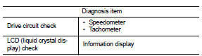
METHOD OF STARTING

METHOD OF STARTING

1. Turn ignition switch ON, and switch the trip meter to “trip A” or “trip B”. 2. Turn ignition switch OFF. 3. While pressing the meter control switch (1), turn ignition switch ON. 4. Make sure that the trip meter displays “0000.0”.

5. Press the meter control switch at least 3 times. (Within 7 seconds after the ignition switch is turned ON.)

6. The combination meter is turned to self-diagnosis mode.

6. The combination meter is turned to self-diagnosis mode.

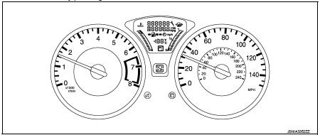
All of the segments of engine coolant temperature gauge, fuel gauge, odo/trip meter, shift position indicator (A) for CVT models and information display illuminate.

NOTE:
• Check combination meter power supply and ground circuit when the self-diagnosis mode of the combination meter does not start. Replace combination meter if power supply and ground circuit are normal. • If any of the dots are not displayed, replace combination meter.

• For M/T models, start-up lamp (B) illuminate instead of shift position indicator.

7. Each meter activates by pressing the meter control switch.
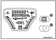

NOTE:

NOTE:
• If any of the meters or gauges is not activated, replace combination meter.

• The figure is reference.

Consult-III Function

CONSULT-III APPLICATION ITEMS

CONSULT-III can perform the following diagnosis modes via CAN communication and the combination meter.

SELF DIAG RESULT

SELF DIAG RESULT

Refer to MWI-36, "DTC Index".

DATA MONITOR

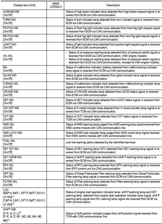
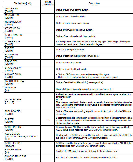
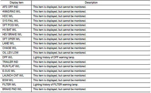
Display Item List
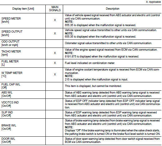


• *1: CVT models

• *1: CVT models
• *2: M/T models
• *3: Without manual mode CVT • *4: With manual mode CVT

NOTE

:
Some items are not available according to vehicle specification.

SPECIAL FUNCTION

Special menu

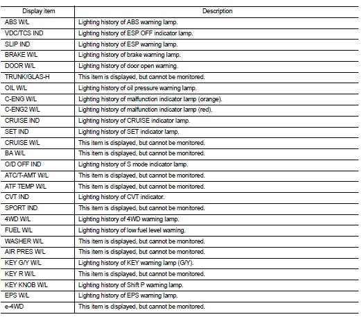
W/L ON HISTORY

W/L ON HISTORY

• Stores histories when warning/indicator lamp is turned on. • “W/L ON HISTORY” indicates the “TIME” when the warning/ indicator lamp is turned on. • The “TIME” above is:
- 0: The condition that the warning/indicator lamp has been turned on 1 or more times after starting the engine and waiting for 30 seconds. - 1 - 39: The number of times the engine was restarted after the 0 condition.

- NO W/L ON HISTORY: Stores NO (0) turning on history of warning/indicator lamp.

NOTE:
• W/L ON HISTORY is not stored for approximately 30 seconds after the engine starts.

• Brake warning lamp does not store any history when the parking brake is applied or the brake fluid level gets low.

Display Item

Ecu diagnosis information