Engine Mechanical MR16DDT

Drive belt

In this manual: Engine Mechanical MR16DDT
Foreword — 1General information — 45Engine Mechanical MR16DDT — 61Engine Mechanical HR16DE — 52Engine Mechanical K9K — 46Engine Lubrication System MR16DDT — 18Engine Lubrication System HR16DE — 14Engine Lubrication System K9K — 11Engine Cooling System MR16DDT — 28Engine Cooling System HR16DE — 29Engine Cooling System K9K — 24Engine Control System MR16DDT — 163Engine Control System HR16DE — 115Engine Control System K9K — 129Fuel System MR16DDT — 13Fuel system HR16DE — 11Fuel system K9K — 12Exhaust system MR16DDT — 7Exhaust system HR16DE — 10Exhaust system K9K — 7Starting system — 24Accelerator control system — 6Clutch — 25Driveline transfer: TY21B — 77Driveline rear propeller Shaft: 3Fφ16-ETJ75 — 12Driveline rear final drive: RTVS — 31Transaxle & transmission 5MT: RS5F92R — 31Transaxle & transmission 6MT: RS6F94R — 30Transaxle & transmission CVT: RE0F10B — 93Transaxle & transmissioN CVT: RE0F11A — 103Front Axle MR16DDT — 18Front Axle HR16DE — 17Front Axle K9K — 17Rear Axle 2WD — 6Rear Axle 4WD — 13Front Suspension — 21Rear Suspension 2WD — 13Rear Suspension 4WD — 17Road Wheels & Tires — 6Brake System LHD — 24Brake System RHD — 24Parking Brake System — 8Brake Control System without ESP — 44Brake Control System with ESP — 63Steering System — 14Steering Control System — 27Seat Belt — 8SRS Airbag — 24SRS Airbag Control System — 93Ventilation System — 11Heater & Air Conditioning System HR16DE — 28Heater & Air Conditioning System MR16DDT — 28Heater & Air Conditioning Control System Type 1 — 49Heater & Air Conditioning Control System Type 2 — 51Heater & Air Conditioning Control System Type 3 — 32Heater & Air Conditioning Control System Type 4 — 40Heater & Air Conditioning Control System Type 5 — 21Interior — 16Instrument Panel — 10Seat — 18Door & Lock Type 1 — 83Door & Lock type 2 — 80Door & Lock type 3 — 65Door & Lock type 4 — 60Security Control System with intelligent key system — 82Security Control System without intelligent key system — 41Glass & Window System — 15Power Window Control System — 28Body Repair — 13Exterior — 20Mirrors — 26Exterior Lighting System Halogen type — 51Interior Lighting System — 24Wiper & Washer — 45Defogger — 31Horn — 4Power Outlet — 4Body Control System With intelligent key system — 21Body Control System Without intelligent key system — 23LAN system can fundamental — 6LAN system can — 31LAN System can system (type 1) — 1LAN System can system (type 2) — 1LAN System can system (type 3) — 1LAN System can system (type 4) — 1LAN System can system (type 5) — 1LAN System can system (type 6) — 1LAN System can system (type 7) — 2LAN System can system (type 8) — 1LAN System can system (type 9) — 1LAN System can system (type 10) — 1LAN System can system (type 11) — 1Power Control System IPDM E/R (with I-key) — 14Power Control System IPDM E/R (without I-key) — 14Power Control System Power distribution system — 25Charging System — 22Power Supply, Ground & Circuit Elements — 20Meter, Warning Lamp & Indicator — 33Warning Chime System — 22Audio, Visual & Navigation System Audio without navigation — 30Audio, Visual & Navigation System Audio with navigation — 33Audio, Visual & Navigation System NISSAN dynamic control system — 22Cruise Control System — 1Drive Mode System — 10Maintenance — 14
~2min read

Exploded View

1. Alternator

1. Alternator
2. Drive belt auto-tensioner 3. Crankshaft pulley
4. A/C compressor
5. Water pump
6. Drive belt

A. Possible use range B.

Range when new drive belt is installed C. Indicator

Checking

WARNING: Perform this step when engine is stopped. • Check that the indicator (C) (notch on fixed side) of drive belt auto-tensioner is within the possible use range (A) in the figure. NOTE:
• Check the drive belt auto-tensioner indication when the engine is cold. • When new drive belt is installed, the indicator (notch on fixed side) should be within the range (B) in the figure. • Visually check entire drive belt for wear, damage or cracks.

• If the indicator (notch on fixed side) is out of the possible use range or belt is damaged, replace drive belt.

Tension Adjustment

Refer to : EM-129, "Drive Belt".

Removal and Installation

REMOVAL

1. Turn the steering wheel to the right. 2. Remove the front fender protector (RH) front side bolts and clips. And keep a service area. Refer to EXT- 22, "Exploded View".

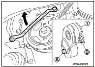
3. Hold the hexagonal part (A) of drive belt auto-tensioner (1) with a wrench securely. Then move the wrench handle in the direction of arrow (loosening direction of tensioner).

CAUTION: Avoid placing hand in a location where pinching may occur if the holding tool accidentally comes off

.

4. Insert a rod approximately 6 mm (0.24 in) in diameter such as short-length screwdriver into the hole (B) of the retaining boss to fix drive belt auto-tensioner. • Keep drive belt auto-tensioner pulley arm locked after drive belt is removed.

5. Remove drive belt.

INSTALLATION

INSTALLATION 1. Install drive belt. CAUTION:
• Confirm drive belt is completely set to pulleys.

• Check for engine oil, working fluid and engine coolant are not adhered to drive belt and each pulley groove

. 2. Release drive belt auto-tensioner, and apply tension to drive belt. 3. Turn crankshaft pulley clockwise several times to equalize tension between each pulley.

4. Confirm tension of drive belt at indicator (notch on fixed side) is within the possible use range. Refer to EM-20, "Exploded View".