Transaxle & transmissioN CVT: RE0F11A

Ecu diagnosis information

In this manual: Transaxle & transmissioN CVT: RE0F11A
Foreword — 1General information — 45Engine Mechanical MR16DDT — 61Engine Mechanical HR16DE — 52Engine Mechanical K9K — 46Engine Lubrication System MR16DDT — 18Engine Lubrication System HR16DE — 14Engine Lubrication System K9K — 11Engine Cooling System MR16DDT — 28Engine Cooling System HR16DE — 29Engine Cooling System K9K — 24Engine Control System MR16DDT — 163Engine Control System HR16DE — 115Engine Control System K9K — 129Fuel System MR16DDT — 13Fuel system HR16DE — 11Fuel system K9K — 12Exhaust system MR16DDT — 7Exhaust system HR16DE — 10Exhaust system K9K — 7Starting system — 24Accelerator control system — 6Clutch — 25Driveline transfer: TY21B — 77Driveline rear propeller Shaft: 3Fφ16-ETJ75 — 12Driveline rear final drive: RTVS — 31Transaxle & transmission 5MT: RS5F92R — 31Transaxle & transmission 6MT: RS6F94R — 30Transaxle & transmission CVT: RE0F10B — 93Transaxle & transmissioN CVT: RE0F11A — 103Front Axle MR16DDT — 18Front Axle HR16DE — 17Front Axle K9K — 17Rear Axle 2WD — 6Rear Axle 4WD — 13Front Suspension — 21Rear Suspension 2WD — 13Rear Suspension 4WD — 17Road Wheels & Tires — 6Brake System LHD — 24Brake System RHD — 24Parking Brake System — 8Brake Control System without ESP — 44Brake Control System with ESP — 63Steering System — 14Steering Control System — 27Seat Belt — 8SRS Airbag — 24SRS Airbag Control System — 93Ventilation System — 11Heater & Air Conditioning System HR16DE — 28Heater & Air Conditioning System MR16DDT — 28Heater & Air Conditioning Control System Type 1 — 49Heater & Air Conditioning Control System Type 2 — 51Heater & Air Conditioning Control System Type 3 — 32Heater & Air Conditioning Control System Type 4 — 40Heater & Air Conditioning Control System Type 5 — 21Interior — 16Instrument Panel — 10Seat — 18Door & Lock Type 1 — 83Door & Lock type 2 — 80Door & Lock type 3 — 65Door & Lock type 4 — 60Security Control System with intelligent key system — 82Security Control System without intelligent key system — 41Glass & Window System — 15Power Window Control System — 28Body Repair — 13Exterior — 20Mirrors — 26Exterior Lighting System Halogen type — 51Interior Lighting System — 24Wiper & Washer — 45Defogger — 31Horn — 4Power Outlet — 4Body Control System With intelligent key system — 21Body Control System Without intelligent key system — 23LAN system can fundamental — 6LAN system can — 31LAN System can system (type 1) — 1LAN System can system (type 2) — 1LAN System can system (type 3) — 1LAN System can system (type 4) — 1LAN System can system (type 5) — 1LAN System can system (type 6) — 1LAN System can system (type 7) — 2LAN System can system (type 8) — 1LAN System can system (type 9) — 1LAN System can system (type 10) — 1LAN System can system (type 11) — 1Power Control System IPDM E/R (with I-key) — 14Power Control System IPDM E/R (without I-key) — 14Power Control System Power distribution system — 25Charging System — 22Power Supply, Ground & Circuit Elements — 20Meter, Warning Lamp & Indicator — 33Warning Chime System — 22Audio, Visual & Navigation System Audio without navigation — 30Audio, Visual & Navigation System Audio with navigation — 33Audio, Visual & Navigation System NISSAN dynamic control system — 22Cruise Control System — 1Drive Mode System — 10Maintenance — 14
~2min read
TCM Reference Value

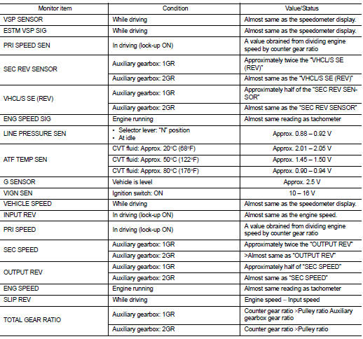
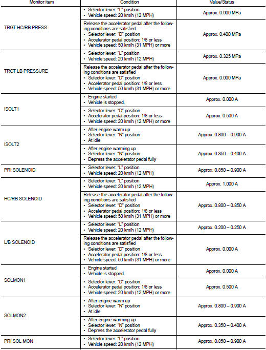
CONSULT-III DATA MONITOR STANDARD VALUE

• In CONSULT-III, electric shift timing or lock-up timing, i.e. operation timing of each solenoid valve, is displayed.

Therefore, if there is an obvious difference between the shift timing estimated from a shift shock (or engine speed variations) and that shown on the CONSULT-III, the mechanism parts (including the hydraulic circuit) excluding the solenoids and sensors may be malfunctioning. In this case, check the mechanical parts following the appropriate diagnosis procedure.

• Shift point (gear position) displayed on CONSULT-III slightly differs from shift pattern described in Service Manual. This is due to the following reasons.

- Actual shift pattern may vary slightly within specified tolerances. - While shift pattern described in Service Manual indicates start of each shift, CONSULT-III shows gear position at end of shift.

- The solenoid display (ON/OFF) on CONSULT-III is changed at the start of gear shifting. In contrast, the gear position display is changed at the time when gear shifting calculated in the control unit is completed.


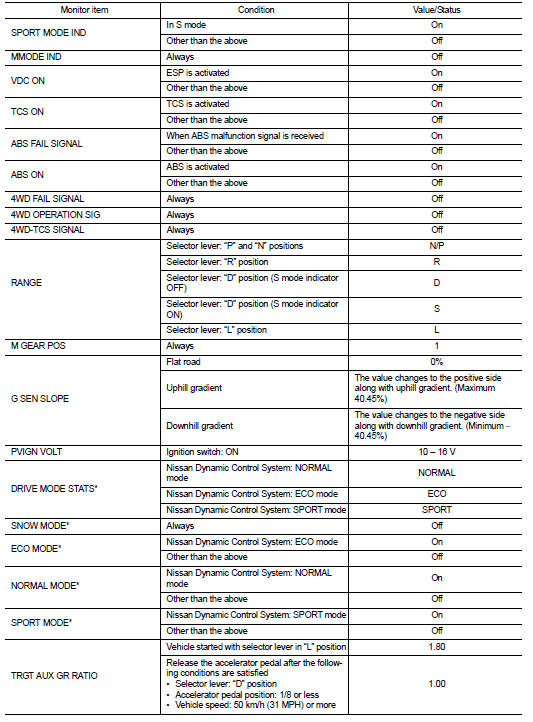

*: With Nissan Dynamic Control System

*: With Nissan Dynamic Control System

TERMINAL LAYOUT
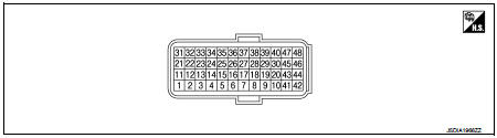
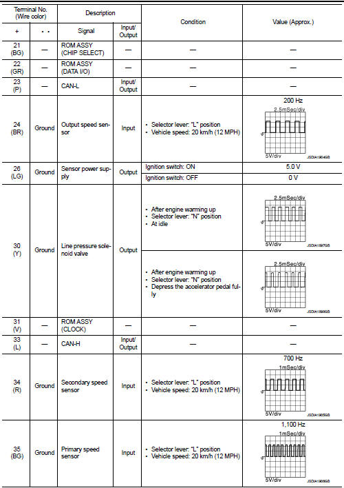
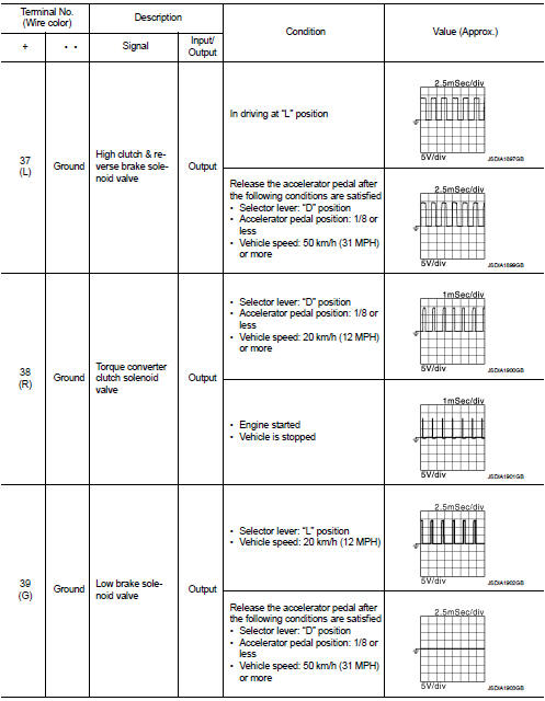
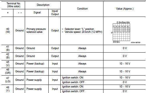
INPUT/OUTPUT SIGNAL STANDARD

INPUT/OUTPUT SIGNAL STANDARD


Fail-Safe

Fail-Safe

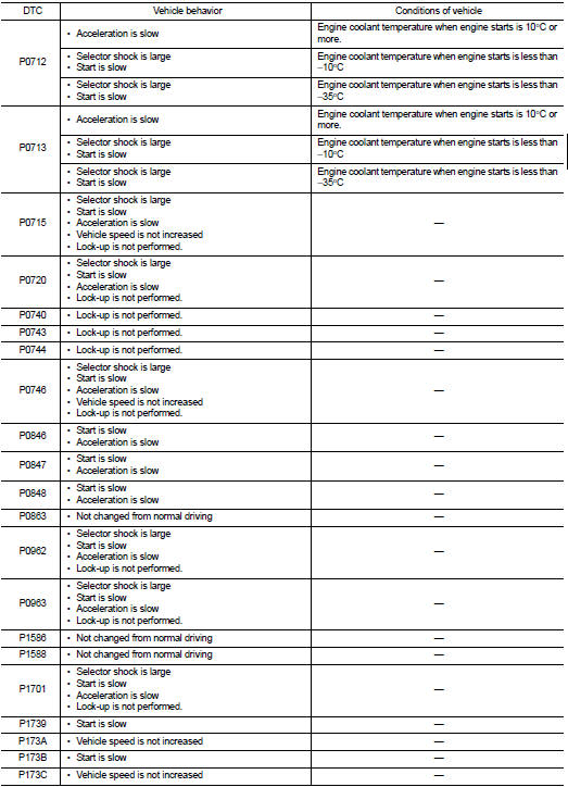
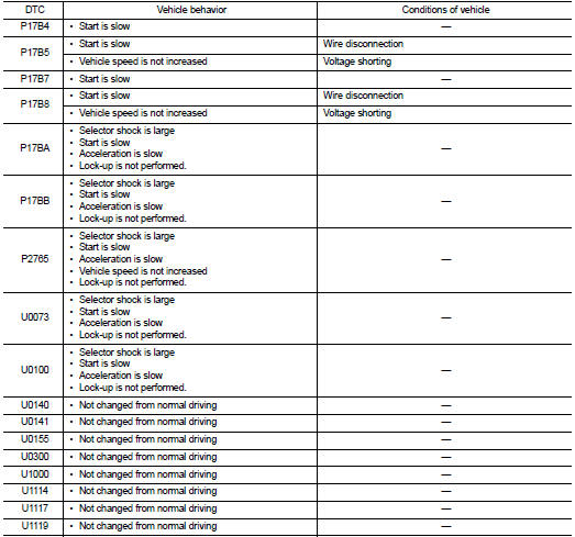
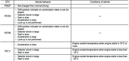
TCM has a fail-safe mode. The mode functions so that operation can be continued even if the signal circuit of the main electronically controlled input/output parts is damaged.

If the vehicle shows following behaviors including "poor acceleration", a malfunction of the applicable system is detected by TCM and the vehicle may be in a fail-safe mode. At this time, check the DTC code and perform inspection and repair according to the malfunction diagnosis procedures.

Fail-safe function


Protection control

Protection control

The TCM becomes the protection control status temporarily to protect the safety when the safety of TCM and transmission is lost. It automatically returns to the normal status if the safety is secured.

The TCM has the following protection control.

CONTROL FOR WHEEL SPIN

CONTROL WHEN FLUID TEMPERATURE IS HIG

CONTROL WHEN FLUID TEMPERATURE IS HIG

TORQUE IS REDUCED WHEN DRIVING WITH THE REVERSE GEAR

TORQUE IS REDUCED WHEN DRIVING WITH THE REVERSE GEAR

REVERSE PROHIBIT CONTRO

REVERSE PROHIBIT CONTRO

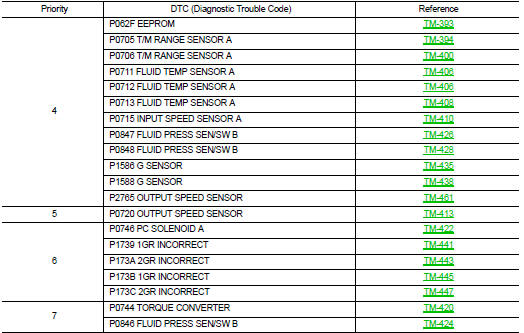
DTC Inspection Priority Chart

DTC Inspection Priority Chart

If multiple malfunction codes are detected at the same time, check each code according to the DTC check priority list below.

DTC Index

DTC Index NOTE:
• If multiple malfunction codes are detected at the same time, check each code according to the "DTC check priority list". TM-365, "DTC Inspection Priority Chart".

• The ignition counter is displayed in “FFD”. Refer to TM-347, "CONSULT-III Function (TRANSMISSION)".

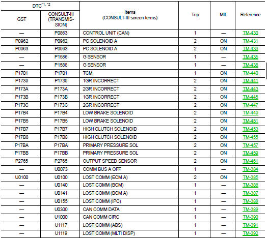
*1: These numbers are specified by SAE J2012/ISO 15031-6.

*1: These numbers are specified by SAE J2012/ISO 15031-6.

*2: The DTC number of the 1st trip is the same as the DTC number.