Power Control System IPDM E/R (with I-key)

ECU diagnosis information

In this manual: Power Control System IPDM E/R (with I-key)
Foreword — 1General information — 45Engine Mechanical MR16DDT — 61Engine Mechanical HR16DE — 52Engine Mechanical K9K — 46Engine Lubrication System MR16DDT — 18Engine Lubrication System HR16DE — 14Engine Lubrication System K9K — 11Engine Cooling System MR16DDT — 28Engine Cooling System HR16DE — 29Engine Cooling System K9K — 24Engine Control System MR16DDT — 163Engine Control System HR16DE — 115Engine Control System K9K — 129Fuel System MR16DDT — 13Fuel system HR16DE — 11Fuel system K9K — 12Exhaust system MR16DDT — 7Exhaust system HR16DE — 10Exhaust system K9K — 7Starting system — 24Accelerator control system — 6Clutch — 25Driveline transfer: TY21B — 77Driveline rear propeller Shaft: 3Fφ16-ETJ75 — 12Driveline rear final drive: RTVS — 31Transaxle & transmission 5MT: RS5F92R — 31Transaxle & transmission 6MT: RS6F94R — 30Transaxle & transmission CVT: RE0F10B — 93Transaxle & transmissioN CVT: RE0F11A — 103Front Axle MR16DDT — 18Front Axle HR16DE — 17Front Axle K9K — 17Rear Axle 2WD — 6Rear Axle 4WD — 13Front Suspension — 21Rear Suspension 2WD — 13Rear Suspension 4WD — 17Road Wheels & Tires — 6Brake System LHD — 24Brake System RHD — 24Parking Brake System — 8Brake Control System without ESP — 44Brake Control System with ESP — 63Steering System — 14Steering Control System — 27Seat Belt — 8SRS Airbag — 24SRS Airbag Control System — 93Ventilation System — 11Heater & Air Conditioning System HR16DE — 28Heater & Air Conditioning System MR16DDT — 28Heater & Air Conditioning Control System Type 1 — 49Heater & Air Conditioning Control System Type 2 — 51Heater & Air Conditioning Control System Type 3 — 32Heater & Air Conditioning Control System Type 4 — 40Heater & Air Conditioning Control System Type 5 — 21Interior — 16Instrument Panel — 10Seat — 18Door & Lock Type 1 — 83Door & Lock type 2 — 80Door & Lock type 3 — 65Door & Lock type 4 — 60Security Control System with intelligent key system — 82Security Control System without intelligent key system — 41Glass & Window System — 15Power Window Control System — 28Body Repair — 13Exterior — 20Mirrors — 26Exterior Lighting System Halogen type — 51Interior Lighting System — 24Wiper & Washer — 45Defogger — 31Horn — 4Power Outlet — 4Body Control System With intelligent key system — 21Body Control System Without intelligent key system — 23LAN system can fundamental — 6LAN system can — 31LAN System can system (type 1) — 1LAN System can system (type 2) — 1LAN System can system (type 3) — 1LAN System can system (type 4) — 1LAN System can system (type 5) — 1LAN System can system (type 6) — 1LAN System can system (type 7) — 2LAN System can system (type 8) — 1LAN System can system (type 9) — 1LAN System can system (type 10) — 1LAN System can system (type 11) — 1Power Control System IPDM E/R (with I-key) — 14Power Control System IPDM E/R (without I-key) — 14Power Control System Power distribution system — 25Charging System — 22Power Supply, Ground & Circuit Elements — 20Meter, Warning Lamp & Indicator — 33Warning Chime System — 22Audio, Visual & Navigation System Audio without navigation — 30Audio, Visual & Navigation System Audio with navigation — 33Audio, Visual & Navigation System NISSAN dynamic control system — 22Cruise Control System — 1Drive Mode System — 10Maintenance — 14
~2min read
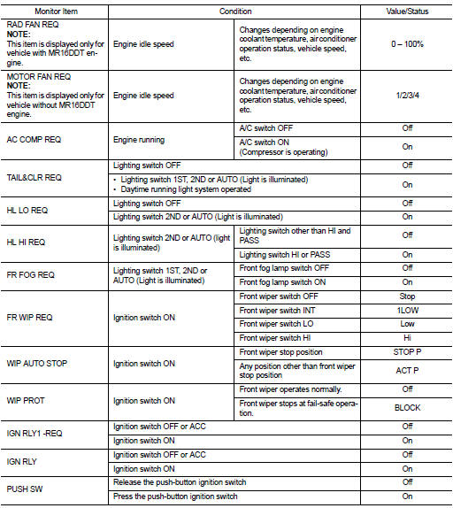
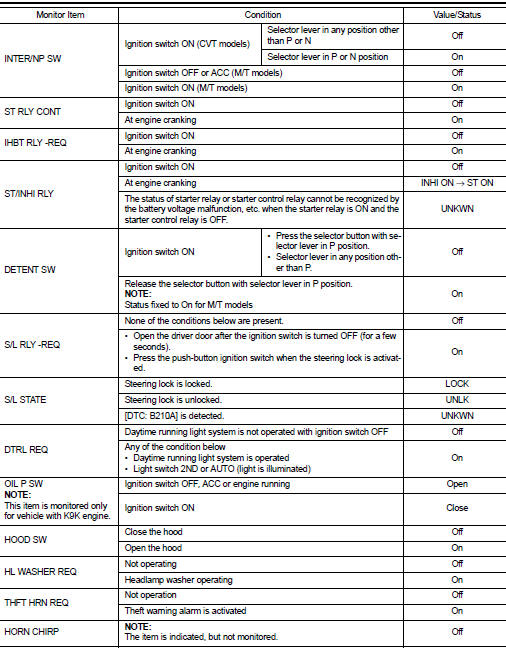
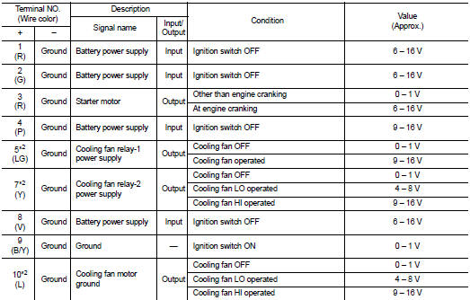
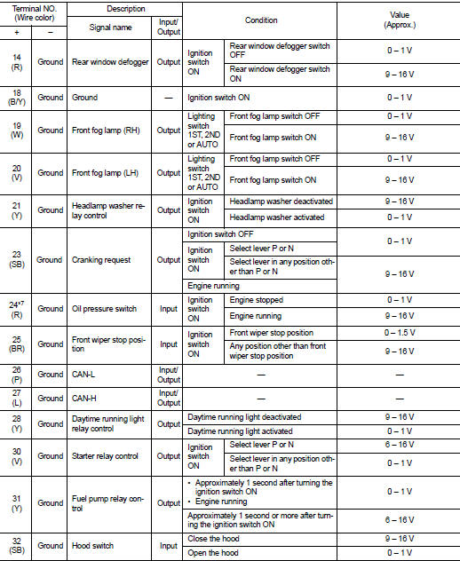
IPDM E/R Reference Value

VALUES ON THE DIAGNOSIS TOOL


TERMINAL LAYOUT
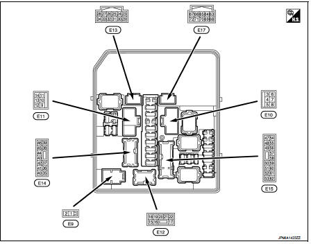
TERMINAL LAYOUT

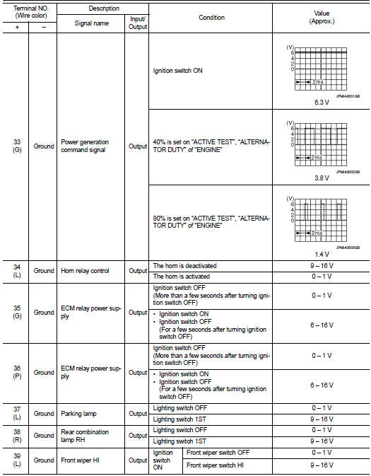
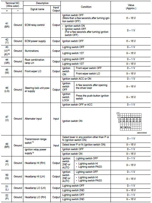
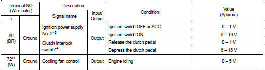
PHYSICAL VALUES
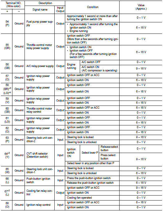
PHYSICAL VALUES


*1: MR16DDT engine models

*1: MR16DDT engine models *2: Except MR16DDT engine models *3: CVT models
*4: M/T models
*5: With daytime running light system *6: Without daytime running light system *7: K9K engine models

Fail-Safe

CAN COMMUNICATION CONTROL

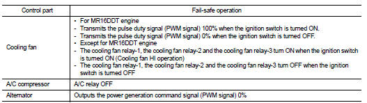
When CAN communication with ECM and BCM is impossible, IPDM E/R performs fail-safe control. After CAN communication recovers normally, it also returns to normal control.

If No CAN Communication Is Available With ECM
If No CAN Communication Is Available With BCM
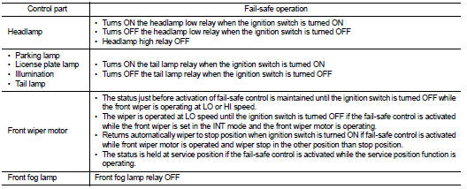
If No CAN Communication Is Available With BCM


IGNITION RELAY MALFUNCTION DETECTION FUNCTION

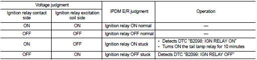
IGNITION RELAY MALFUNCTION DETECTION FUNCTION

• IPDM E/R monitors the voltage at the contact circuit and excitation coil circuit of the ignition relay inside it. • IPDM E/R judges the ignition relay error if the voltage differs between the contact circuit and the excitation coil circuit.

• If the ignition relay cannot turn OFF due to contact seizure, it activates the tail lamp relay for 10 minutes to alert the user to the ignition relay malfunction when the ignition switch is turned OFF.
FRONT WIPER PROTECTION FUNCTION

FRONT WIPER PROTECTION FUNCTION

IPDM E/R detects front wiper stop position by a front wiper stop position signal.

When a front wiper stop position signal is in the conditions listed below, IPDM E/R stops power supply to wiper after repeating a front wiper 10 seconds activation and 20 seconds stop.

NOTE:

NOTE

:
This operation status can be confirmed on the IPDM E/R “Data Monitor” that displays “BLOCK” for the item “WIP PROT” while the wiper is stopped.

STARTER MOTOR PROTECTION FUNCTION

IPDM E/R turns OFF the starter control relay to protect the starter motor when the starter control relay remains active for 90 seconds.

DTC Index NOTE:
• The details of time display are as follows. - CRNT: A malfunction is detected now.

- PAST: A malfunction was detected in the past.

• IGN counter is displayed on FFD (Freeze Frame Data). - The number is 0 when is detected now. - The number increases like 1 → 2 ··· 38 → 39 after returning to the normal condition whenever IGN OFF → ON.

- The number is fixed to 39 until the self-diagnosis results are erased if it is over 39.


Wiring diagram