Engine Control System HR16DE

General Precautions

In this manual: Engine Control System HR16DE
Foreword — 1General information — 45Engine Mechanical MR16DDT — 61Engine Mechanical HR16DE — 52Engine Mechanical K9K — 46Engine Lubrication System MR16DDT — 18Engine Lubrication System HR16DE — 14Engine Lubrication System K9K — 11Engine Cooling System MR16DDT — 28Engine Cooling System HR16DE — 29Engine Cooling System K9K — 24Engine Control System MR16DDT — 163Engine Control System HR16DE — 115Engine Control System K9K — 129Fuel System MR16DDT — 13Fuel system HR16DE — 11Fuel system K9K — 12Exhaust system MR16DDT — 7Exhaust system HR16DE — 10Exhaust system K9K — 7Starting system — 24Accelerator control system — 6Clutch — 25Driveline transfer: TY21B — 77Driveline rear propeller Shaft: 3Fφ16-ETJ75 — 12Driveline rear final drive: RTVS — 31Transaxle & transmission 5MT: RS5F92R — 31Transaxle & transmission 6MT: RS6F94R — 30Transaxle & transmission CVT: RE0F10B — 93Transaxle & transmissioN CVT: RE0F11A — 103Front Axle MR16DDT — 18Front Axle HR16DE — 17Front Axle K9K — 17Rear Axle 2WD — 6Rear Axle 4WD — 13Front Suspension — 21Rear Suspension 2WD — 13Rear Suspension 4WD — 17Road Wheels & Tires — 6Brake System LHD — 24Brake System RHD — 24Parking Brake System — 8Brake Control System without ESP — 44Brake Control System with ESP — 63Steering System — 14Steering Control System — 27Seat Belt — 8SRS Airbag — 24SRS Airbag Control System — 93Ventilation System — 11Heater & Air Conditioning System HR16DE — 28Heater & Air Conditioning System MR16DDT — 28Heater & Air Conditioning Control System Type 1 — 49Heater & Air Conditioning Control System Type 2 — 51Heater & Air Conditioning Control System Type 3 — 32Heater & Air Conditioning Control System Type 4 — 40Heater & Air Conditioning Control System Type 5 — 21Interior — 16Instrument Panel — 10Seat — 18Door & Lock Type 1 — 83Door & Lock type 2 — 80Door & Lock type 3 — 65Door & Lock type 4 — 60Security Control System with intelligent key system — 82Security Control System without intelligent key system — 41Glass & Window System — 15Power Window Control System — 28Body Repair — 13Exterior — 20Mirrors — 26Exterior Lighting System Halogen type — 51Interior Lighting System — 24Wiper & Washer — 45Defogger — 31Horn — 4Power Outlet — 4Body Control System With intelligent key system — 21Body Control System Without intelligent key system — 23LAN system can fundamental — 6LAN system can — 31LAN System can system (type 1) — 1LAN System can system (type 2) — 1LAN System can system (type 3) — 1LAN System can system (type 4) — 1LAN System can system (type 5) — 1LAN System can system (type 6) — 1LAN System can system (type 7) — 2LAN System can system (type 8) — 1LAN System can system (type 9) — 1LAN System can system (type 10) — 1LAN System can system (type 11) — 1Power Control System IPDM E/R (with I-key) — 14Power Control System IPDM E/R (without I-key) — 14Power Control System Power distribution system — 25Charging System — 22Power Supply, Ground & Circuit Elements — 20Meter, Warning Lamp & Indicator — 33Warning Chime System — 22Audio, Visual & Navigation System Audio without navigation — 30Audio, Visual & Navigation System Audio with navigation — 33Audio, Visual & Navigation System NISSAN dynamic control system — 22Cruise Control System — 1Drive Mode System — 10Maintenance — 14
~3min read
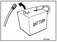
• Always use a 12 volt battery as power source. • Do not attempt to disconnect battery cables while engine is running. • Before connecting or disconnecting the ECM harness connector, turn ignition switch OFF and disconnect negative battery cable. Failure to do so may damage the ECM because battery voltage is applied to ECM even if ignition switch is turned OFF.

• Before removing parts, turn ignition switch OFF and then disconnect battery ground cable.
• Do not disassemble ECM.

• Do not disassemble ECM.

• If a battery cable is disconnected, the memory will return to the ECM value.

The ECM will now start to self-control at its initial value. So, engine operation can vary slightly in this case. However, this is not an indication of a malfunction. Do not replace parts because of a slight variation.

• If the battery is disconnected, the following emission-related diagnostic information will be lost within 24 hours.

- Diagnostic trouble codes - 1st trip diagnostic trouble codes - Freeze frame data
- 1st trip freeze frame data - System readiness test (SRT) codes - Test values

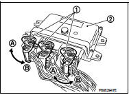
• When connecting ECM harness connector (1), fasten (B) it securely with a lever as far as it will go as shown in the figure.

- ECM (2)
- Loosen (A)


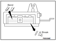
• When connecting or disconnecting pin connectors into or

• When connecting or disconnecting pin connectors into or from ECM, take care not to damage pin terminals (bend or break). Make sure that there are not any bends or breaks on ECM pin terminal, when connecting pin connectors.

• Securely connect ECM harness connectors.

A poor connection can cause an extremely high (surge) voltage to develop in coil and condenser, thus resulting in damage to ICs. • Keep engine control system harness at least 10 cm (4 in) away from adjacent harness, to prevent engine control system malfunctions due to receiving external noise, degraded operation of ICs, etc. • Keep engine control system parts and harness dry.

• Before replacing ECM, perform ECM Terminals and Reference Value inspection and make sure ECM functions properly.

Refer to EC-508, "Reference Value". • Handle mass air flow sensor carefully to avoid damage. • Do not clean mass air flow sensor with any type of detergent. • Do not disassemble electric throttle control actuator. • Even a slight leak in the air intake system can cause serious incidents.

• Do not shock or jar the camshaft position sensor (PHASE), crankshaft position sensor (POS).

• After performing each TROUBLE DIAGNOSIS, perform DTC

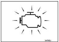
• After performing each TROUBLE DIAGNOSIS, perform DTC CONFIRMATION PROCEDURE or Component Function Check. The DTC should not be displayed in the DTC CONFIRMATION PROCEDURE if the repair is completed. The Component Function Check should be a good result if the repair is completed.
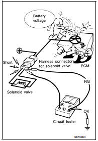
• When measuring ECM signals with a circuit tester, never allow

• When measuring ECM signals with a circuit tester, never allow the two tester probes to contact.

Accidental contact of probes will cause a short circuit and damage the ECM power transistor.
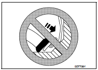
• Do not operate fuel pump when there is no fuel in lines.

• Do not operate fuel pump when there is no fuel in lines. • Tighten fuel hose clamps to the specified torque. • Do not depress accelerator pedal when starting. • Immediately after starting, do not rev up engine unnecessarily.

• Do not rev up engine just prior to shutdown.
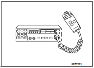
• When installing C.B. ham radio or a mobile phone, be sure to

• When installing C.B. ham radio or a mobile phone, be sure to observe the following as it may adversely affect electronic control systems depending on installation location.

- Keep the antenna as far as possible from the electronic control units. - Keep the antenna feeder line more than 20 cm (8 in) away from the harness of electronic controls. Do not let them run parallel for a long distance. - Adjust the antenna and feeder line so that the standing-wave ratio can be kept smaller.

- Be sure to ground the radio to vehicle body.
Preparation