Starting system

HR16DE : Inspection and Adjust

In this manual: Starting system
Foreword — 1General information — 45Engine Mechanical MR16DDT — 61Engine Mechanical HR16DE — 52Engine Mechanical K9K — 46Engine Lubrication System MR16DDT — 18Engine Lubrication System HR16DE — 14Engine Lubrication System K9K — 11Engine Cooling System MR16DDT — 28Engine Cooling System HR16DE — 29Engine Cooling System K9K — 24Engine Control System MR16DDT — 163Engine Control System HR16DE — 115Engine Control System K9K — 129Fuel System MR16DDT — 13Fuel system HR16DE — 11Fuel system K9K — 12Exhaust system MR16DDT — 7Exhaust system HR16DE — 10Exhaust system K9K — 7Starting system — 24Accelerator control system — 6Clutch — 25Driveline transfer: TY21B — 77Driveline rear propeller Shaft: 3Fφ16-ETJ75 — 12Driveline rear final drive: RTVS — 31Transaxle & transmission 5MT: RS5F92R — 31Transaxle & transmission 6MT: RS6F94R — 30Transaxle & transmission CVT: RE0F10B — 93Transaxle & transmissioN CVT: RE0F11A — 103Front Axle MR16DDT — 18Front Axle HR16DE — 17Front Axle K9K — 17Rear Axle 2WD — 6Rear Axle 4WD — 13Front Suspension — 21Rear Suspension 2WD — 13Rear Suspension 4WD — 17Road Wheels & Tires — 6Brake System LHD — 24Brake System RHD — 24Parking Brake System — 8Brake Control System without ESP — 44Brake Control System with ESP — 63Steering System — 14Steering Control System — 27Seat Belt — 8SRS Airbag — 24SRS Airbag Control System — 93Ventilation System — 11Heater & Air Conditioning System HR16DE — 28Heater & Air Conditioning System MR16DDT — 28Heater & Air Conditioning Control System Type 1 — 49Heater & Air Conditioning Control System Type 2 — 51Heater & Air Conditioning Control System Type 3 — 32Heater & Air Conditioning Control System Type 4 — 40Heater & Air Conditioning Control System Type 5 — 21Interior — 16Instrument Panel — 10Seat — 18Door & Lock Type 1 — 83Door & Lock type 2 — 80Door & Lock type 3 — 65Door & Lock type 4 — 60Security Control System with intelligent key system — 82Security Control System without intelligent key system — 41Glass & Window System — 15Power Window Control System — 28Body Repair — 13Exterior — 20Mirrors — 26Exterior Lighting System Halogen type — 51Interior Lighting System — 24Wiper & Washer — 45Defogger — 31Horn — 4Power Outlet — 4Body Control System With intelligent key system — 21Body Control System Without intelligent key system — 23LAN system can fundamental — 6LAN system can — 31LAN System can system (type 1) — 1LAN System can system (type 2) — 1LAN System can system (type 3) — 1LAN System can system (type 4) — 1LAN System can system (type 5) — 1LAN System can system (type 6) — 1LAN System can system (type 7) — 2LAN System can system (type 8) — 1LAN System can system (type 9) — 1LAN System can system (type 10) — 1LAN System can system (type 11) — 1Power Control System IPDM E/R (with I-key) — 14Power Control System IPDM E/R (without I-key) — 14Power Control System Power distribution system — 25Charging System — 22Power Supply, Ground & Circuit Elements — 20Meter, Warning Lamp & Indicator — 33Warning Chime System — 22Audio, Visual & Navigation System Audio without navigation — 30Audio, Visual & Navigation System Audio with navigation — 33Audio, Visual & Navigation System NISSAN dynamic control system — 22Cruise Control System — 1Drive Mode System — 10Maintenance — 14
~3min read

INSPECTION

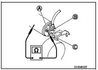
Magnetic Switch Check • Before starting to check, disconnect the battery cable from the negative terminal.

• Disconnect “M” terminal of starter motor.

1. Continuity test [between “S” terminal (A) and switch body]

B : “B” terminal
C : “M” terminal

• Replace magnetic switch if continuity does not exist.
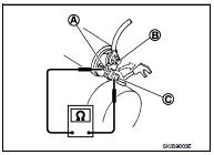
2. Continuity test [between “S” terminal (A) and “M” terminal (C)]

2. Continuity test [between “S” terminal (A) and “M” terminal (C)]

B : “B” terminal

• Replace magnetic switch if continuity does not exist.
Pinion/Clutch Check

Pinion/Clutch Check
1. Inspect pinion teeth.

• Replace pinion if teeth are worn or damaged. (Also check condition of ring gear teeth.) 2. Inspect reduction gear teeth (If equipped).

• Replace reduction gear if teeth are worn or damaged. (Also check condition of armature shaft gear teeth.) 3. Check to see if pinion locks in one direction and rotates smoothly in the opposite direction.

• Replace pinion assembly if it is locked or rotated in both directions or unusual resistance is evident.

Brush Check

Brush Check
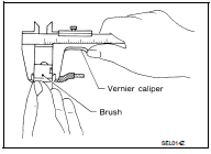
• Check wear of brush.

Minimum length of brush : Refer to SDS STR-35, "Starter Motor".

• Replace brush if the measurement value is less than the specified value.
Brush Spring Check

Brush Spring Check
• Check brush spring tension with brush spring detached from brush.

Spring tension (with new brush) : Refer to SDS STR-35, "Starter Motor".

• Replace brush spring if the measurement value is less than the specified value.

Brush Holder Check

Brush Holder Check
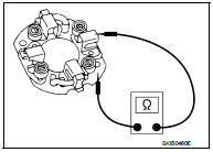
1. Perform insulation test between brush holder (positive side) and its base (negative side).

• Replace brush holder assembly if continuity does not exist.

2. Check brush to see if it moves smoothly.

• If brush holder is bent, replace it; if sliding surface is dirty, clean.
Yoke Check

Yoke Check
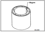
Magnet is secured to yoke by bonding agent. Check magnet to see that it is secured to yoke and for any cracks. Replace malfunctioning parts as an assembly.

CAUTION:
Never clamp yoke in a vise or strike it with a hammer.
Armature Check

Armature Check
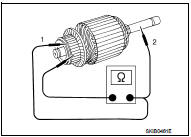
1. Continuity test (between two segments side by side) • Replace armature assembly if continuity does not exist.

2. Insulation test (between each commutator bar and shaft) • Replace armature assembly if continuity exists.
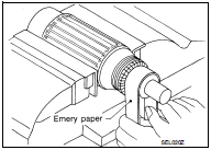
3. Check commutator surface.

3. Check commutator surface.

• Grind with No. 500 - 600 emery paper if it has a rough surface.
4. Check diameter of commutator.

4. Check diameter of commutator.

Commutator minimum diameter : Refer to SDS STR-35, "Starter Motor".

• Replace armature assembly if the measurement value is less than the specified value.

5. Check depth of insulating mold from commutator surface.

5. Check depth of insulating mold from commutator surface.

• Undercut to 0.5 to 0.8 mm (0.020 to 0.031 in) if the depth is 0.2 mm (0.008 in) or less.

ADJUSTMENT

ADJUSTMENT

Pinion Protrusion Length Adjustment

CLEARANCE

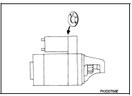
• With pinion driven out by magnetic switch, push pinion back to remove slack and measure clearance “L” between the front edge of the pinion and the pinion stopper.

Clearance “L” : Refer to SDS STR-35, "Starter Motor".

• Adjust with the adjusting plate if the measurement value is not in

• Adjust with the adjusting plate if the measurement value is not in the specified area.
MR16DDT : Exploded View