Transaxle & transmission 6MT: RS6F94R

Input shaft and gear

In this manual: Transaxle & transmission 6MT: RS6F94R
Foreword — 1General information — 45Engine Mechanical MR16DDT — 61Engine Mechanical HR16DE — 52Engine Mechanical K9K — 46Engine Lubrication System MR16DDT — 18Engine Lubrication System HR16DE — 14Engine Lubrication System K9K — 11Engine Cooling System MR16DDT — 28Engine Cooling System HR16DE — 29Engine Cooling System K9K — 24Engine Control System MR16DDT — 163Engine Control System HR16DE — 115Engine Control System K9K — 129Fuel System MR16DDT — 13Fuel system HR16DE — 11Fuel system K9K — 12Exhaust system MR16DDT — 7Exhaust system HR16DE — 10Exhaust system K9K — 7Starting system — 24Accelerator control system — 6Clutch — 25Driveline transfer: TY21B — 77Driveline rear propeller Shaft: 3Fφ16-ETJ75 — 12Driveline rear final drive: RTVS — 31Transaxle & transmission 5MT: RS5F92R — 31Transaxle & transmission 6MT: RS6F94R — 30Transaxle & transmission CVT: RE0F10B — 93Transaxle & transmissioN CVT: RE0F11A — 103Front Axle MR16DDT — 18Front Axle HR16DE — 17Front Axle K9K — 17Rear Axle 2WD — 6Rear Axle 4WD — 13Front Suspension — 21Rear Suspension 2WD — 13Rear Suspension 4WD — 17Road Wheels & Tires — 6Brake System LHD — 24Brake System RHD — 24Parking Brake System — 8Brake Control System without ESP — 44Brake Control System with ESP — 63Steering System — 14Steering Control System — 27Seat Belt — 8SRS Airbag — 24SRS Airbag Control System — 93Ventilation System — 11Heater & Air Conditioning System HR16DE — 28Heater & Air Conditioning System MR16DDT — 28Heater & Air Conditioning Control System Type 1 — 49Heater & Air Conditioning Control System Type 2 — 51Heater & Air Conditioning Control System Type 3 — 32Heater & Air Conditioning Control System Type 4 — 40Heater & Air Conditioning Control System Type 5 — 21Interior — 16Instrument Panel — 10Seat — 18Door & Lock Type 1 — 83Door & Lock type 2 — 80Door & Lock type 3 — 65Door & Lock type 4 — 60Security Control System with intelligent key system — 82Security Control System without intelligent key system — 41Glass & Window System — 15Power Window Control System — 28Body Repair — 13Exterior — 20Mirrors — 26Exterior Lighting System Halogen type — 51Interior Lighting System — 24Wiper & Washer — 45Defogger — 31Horn — 4Power Outlet — 4Body Control System With intelligent key system — 21Body Control System Without intelligent key system — 23LAN system can fundamental — 6LAN system can — 31LAN System can system (type 1) — 1LAN System can system (type 2) — 1LAN System can system (type 3) — 1LAN System can system (type 4) — 1LAN System can system (type 5) — 1LAN System can system (type 6) — 1LAN System can system (type 7) — 2LAN System can system (type 8) — 1LAN System can system (type 9) — 1LAN System can system (type 10) — 1LAN System can system (type 11) — 1Power Control System IPDM E/R (with I-key) — 14Power Control System IPDM E/R (without I-key) — 14Power Control System Power distribution system — 25Charging System — 22Power Supply, Ground & Circuit Elements — 20Meter, Warning Lamp & Indicator — 33Warning Chime System — 22Audio, Visual & Navigation System Audio without navigation — 30Audio, Visual & Navigation System Audio with navigation — 33Audio, Visual & Navigation System NISSAN dynamic control system — 22Cruise Control System — 1Drive Mode System — 10Maintenance — 14
~4min read

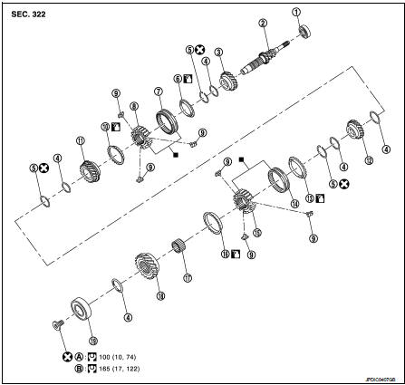
Exploded View

1. Input shaft front bearing

1. Input shaft front bearing 2. Input shaft
3. 3rd input gear
4. Spacer
5. Snap ring
6. 3rd baulk ring
7. 3rd-4th coupling sleeve 8. 3rd-4th synchronizer hub 9. Insert key
10. 4th baulk ring
11. 4th input gear
12. 5th input gear
13. 5th baulk ring
14. 5th-6th coupling sleeve 15. 5th-6th synchronizer hub 16. 6th baulk ring
17. Needle bearing 18. 6th input gear 19. Input shaft rear bearing

A. First step B. Final step

: Replace the parts as a set.: Apply gear oil.
: Always replace after every: Replace the parts as a set.
disassembly.: Always replace after every
disassembly.

Disassembly: N·m (kg-m, ft-lb)


Disassembly

CAUTION:
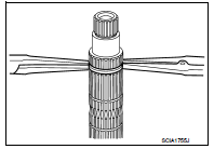
• Fix input shaft in a vise with back plate, and then remove gears and snap rings. • For removal of snap ring, set snap ring pliers and flat pliers at both sides of snap ring. While expanding snap ring with snap ring pliers, move snap ring with flat pliers.

• Disassemble gear components putting direction marks on the parts that do not affect any functions.
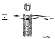
1. Remove input shaft rear bearing mounting bolt (1), using the

1. Remove input shaft rear bearing mounting bolt (1), using the drift (A) [SST: KV32300QAM].
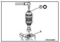
2. Remove input shaft rear bearing (1), as per the following procedure.

2. Remove input shaft rear bearing (1), as per the following procedure.

a. Set a puller [Commercial service tool] to input shaft rear bearing.

b. Remove input shaft rear bearing, using a drift (A) [Commercial service tool].
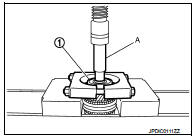
3. Remove spacer (1), 6th input gear (2), needle bearing, 6th baulk

3. Remove spacer (1), 6th input gear (2), needle bearing, 6th baulk ring, and 5th-6th synchronizer hub assembly (3).

4. Remove insert keys and 5th-6th coupling sleeve from 5th-6th synchronizer hub.
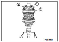
5. Remove snap ring (1).

5. Remove snap ring (1).

6. Remove spacer, 5th baulk ring, 5th input gear (2), and spacer.
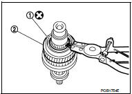
7. Remove snap ring (1).

7. Remove snap ring (1). 8. Remove spacer, 4th input gear (2), 4th baulk ring, and 3rd-4th synchronizer hub assembly (3).

9. Remove insert keys and 3rd-4th coupling sleeve from 3rd-4th synchronizer hub.
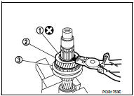
10. Remove snap ring (1).

10. Remove snap ring (1).

11. Remove spacer, 3rd baulk ring, and 3rd input gear (2).
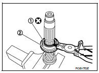
12. Set a puller [Commercial service tool] to input shaft front bearing

12. Set a puller [Commercial service tool] to input shaft front bearing (1), and then remove input shaft front bearing.
Assembly

Assembly

Note the following procedures, and assemble in the reverse order of disassembly.

CAUTION:
• Replace transaxle assembly when replacing input shaft. • For installation of snap ring, set snap ring pliers and flat pliers at both sides of snap ring. While expanding snap ring with snap ring pliers, move snap ring with flat pliers. • Never reuse snap ring. • Check that snap ring is securely installed in a groove. • Replace 3rd-4th coupling sleeve and 3rd-4th synchronizer hub as a set.

• Replace 5th-6th coupling sleeve and 5th-6th synchronizer hub as a set.
• Be careful to install 3rd-4th synchronizer hub according to the

• Be careful to install 3rd-4th synchronizer hub according to the specified direction.

A : 3rd input gear side B : 4th input gear side
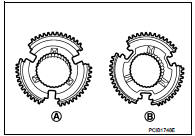
• Be careful to install 5th-6th synchronizer hub according to the

• Be careful to install 5th-6th synchronizer hub according to the specified direction.

A : 5th input gear side B : 6th input gear side

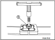
• Install input shaft front bearing (1), using a drift (A) [Commercial

• Install input shaft front bearing (1), using a drift (A) [Commercial service tool].
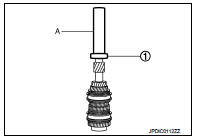
• Install input shaft rear bearing (1), using a drift (A) [Commercial

• Install input shaft rear bearing (1), using a drift (A) [Commercial service tool] and the drift (B) [SST: ST36720030].

• Apply gear oil to 3rd baulk ring, 4th baulk ring, 5th baulk ring, and 6th baulk ring.
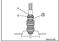
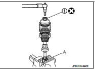
• Install input shaft rear bearing mounting bolt (1), as per the following

• Install input shaft rear bearing mounting bolt (1), as per the following procedure.

CAUTION:
Follow the procedures. Otherwise it may cause a transaxle malfunction.
1. Fix the drift (A) [SST: KV32300QAM] in a vise, and then set input shaft assembly. 2. Install input shaft rear bearing mounting bolt, and then tighten it to the specified torque of the first step. 3. Loosen input shaft rear bearing mounting bolt by a half turn.

4. Tighten input shaft rear bearing mounting bolt to the specified torque of the final step.
Inspection

Inspection

INSPECTION AFTER DISASSEMBLY

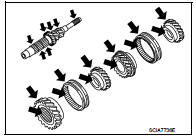
Input Shaft and Gear
Check the following items and replace if necessary.

• Damage, peeling, bend, uneven wear, and distortion of shaft.

• Excessive wear, damage, and peeling of gear.
Synchronizer Hub and Coupling Sleeve

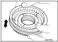
Synchronizer Hub and Coupling Sleeve Check the following items and replace if necessary.

• Breakage, damage, and unusual wear on contact surface of coupling sleeve, synchronizer hub, and insert key.

• Coupling sleeve and synchronizer hub move smoothly.
Baulk Ring

Baulk Ring
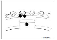
Check contact surface of baulk ring cam and insert key for excessive wear, uneven wear, bend, and damage. Replace if necessary.
Bearing

Bearing
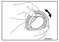
Check bearing for damage and unsmooth rotation. Replace if necessary.
Mainshaft and gear