Engine Cooling System K9K

Precaution for Liquid Gasket

In this manual: Engine Cooling System K9K
Foreword — 1General information — 45Engine Mechanical MR16DDT — 61Engine Mechanical HR16DE — 52Engine Mechanical K9K — 46Engine Lubrication System MR16DDT — 18Engine Lubrication System HR16DE — 14Engine Lubrication System K9K — 11Engine Cooling System MR16DDT — 28Engine Cooling System HR16DE — 29Engine Cooling System K9K — 24Engine Control System MR16DDT — 163Engine Control System HR16DE — 115Engine Control System K9K — 129Fuel System MR16DDT — 13Fuel system HR16DE — 11Fuel system K9K — 12Exhaust system MR16DDT — 7Exhaust system HR16DE — 10Exhaust system K9K — 7Starting system — 24Accelerator control system — 6Clutch — 25Driveline transfer: TY21B — 77Driveline rear propeller Shaft: 3Fφ16-ETJ75 — 12Driveline rear final drive: RTVS — 31Transaxle & transmission 5MT: RS5F92R — 31Transaxle & transmission 6MT: RS6F94R — 30Transaxle & transmission CVT: RE0F10B — 93Transaxle & transmissioN CVT: RE0F11A — 103Front Axle MR16DDT — 18Front Axle HR16DE — 17Front Axle K9K — 17Rear Axle 2WD — 6Rear Axle 4WD — 13Front Suspension — 21Rear Suspension 2WD — 13Rear Suspension 4WD — 17Road Wheels & Tires — 6Brake System LHD — 24Brake System RHD — 24Parking Brake System — 8Brake Control System without ESP — 44Brake Control System with ESP — 63Steering System — 14Steering Control System — 27Seat Belt — 8SRS Airbag — 24SRS Airbag Control System — 93Ventilation System — 11Heater & Air Conditioning System HR16DE — 28Heater & Air Conditioning System MR16DDT — 28Heater & Air Conditioning Control System Type 1 — 49Heater & Air Conditioning Control System Type 2 — 51Heater & Air Conditioning Control System Type 3 — 32Heater & Air Conditioning Control System Type 4 — 40Heater & Air Conditioning Control System Type 5 — 21Interior — 16Instrument Panel — 10Seat — 18Door & Lock Type 1 — 83Door & Lock type 2 — 80Door & Lock type 3 — 65Door & Lock type 4 — 60Security Control System with intelligent key system — 82Security Control System without intelligent key system — 41Glass & Window System — 15Power Window Control System — 28Body Repair — 13Exterior — 20Mirrors — 26Exterior Lighting System Halogen type — 51Interior Lighting System — 24Wiper & Washer — 45Defogger — 31Horn — 4Power Outlet — 4Body Control System With intelligent key system — 21Body Control System Without intelligent key system — 23LAN system can fundamental — 6LAN system can — 31LAN System can system (type 1) — 1LAN System can system (type 2) — 1LAN System can system (type 3) — 1LAN System can system (type 4) — 1LAN System can system (type 5) — 1LAN System can system (type 6) — 1LAN System can system (type 7) — 2LAN System can system (type 8) — 1LAN System can system (type 9) — 1LAN System can system (type 10) — 1LAN System can system (type 11) — 1Power Control System IPDM E/R (with I-key) — 14Power Control System IPDM E/R (without I-key) — 14Power Control System Power distribution system — 25Charging System — 22Power Supply, Ground & Circuit Elements — 20Meter, Warning Lamp & Indicator — 33Warning Chime System — 22Audio, Visual & Navigation System Audio without navigation — 30Audio, Visual & Navigation System Audio with navigation — 33Audio, Visual & Navigation System NISSAN dynamic control system — 22Cruise Control System — 1Drive Mode System — 10Maintenance — 14
~2min read

REMOVAL OF LIQUID GASKET

• After removing the mounting bolts and nuts, separate the mating surface using a seal cutter and remove the liquid gasket.

CAUTION:
Be careful not to damage the mating surfaces.

• In areas where the cutter is difficult to use, use a plastic hammer to lightly tap the gasket applied area.

CAUTION:
If for some unavoidable reason a tool such as a flat-bladed screwdriver is used, be careful not to damage the mating surfaces

.

LIQUID GASKET APPLICATION PROCEDURE

LIQUID GASKET APPLICATION PROCEDURE

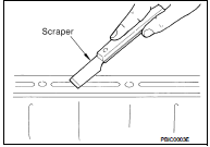
1. Using a scraper, remove the old liquid gasket adhering to the gasket application surface and the mating surface.

• Remove the liquid gasket completely from the groove of the gasket application surface, mounting bolts and bolt holes.

2. Wipe the gasket application surface and the mating surface with white gasoline (lighting and heating use) to remove adhering moisture, grease and foreign materials.

3. Attach the liquid gasket to the tube presser.

Use Genuine Liquid Gasket or equivalent.
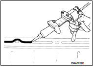
4. Apply the gasket without breaks to the specified location with the

4. Apply the gasket without breaks to the specified location with the specified dimensions.

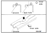
• If there is a groove for the liquid gasket application, apply the gasket to the groove.
• As for the bolt holes, normally apply the gasket inside the

• As for the bolt holes, normally apply the gasket inside the holes. If specified, it should be applied outside the holes. Make sure to read the instruction in this manual. • Within five minutes of gasket application, install the mating component. • If the liquid gasket protrudes, wipe it off immediately. • Do not retighten after the installation.

• After 30 minutes or more have passed from the installation, fill the engine oil and coolant.

CAUTION:
If there are instructions in this manual, observe them.
Preparation