Driveline transfer: TY21B
Structure and operation
In this manual: Driveline transfer: TY21B
~1min read
Sectional View
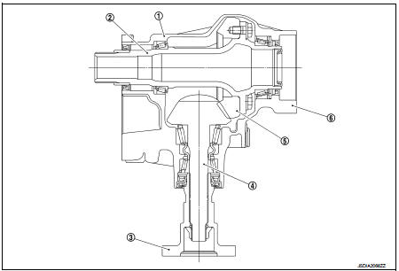
1. Transfer cover
2. Ring gear shaft
3. Companion flange
4. Drive pinion
5. Ring gear
6. Transfer case
Operation Principle
POWER TRANSFER DIAGRAM
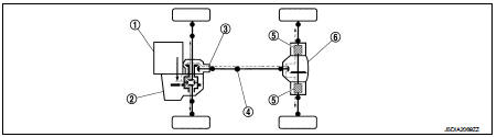
1. Engine
2. Transaxle
3. Transfer
4. Propeller shaft
5. Electric controlled coupling 6. Rear final drive
ELECTRIC CONTROLLED COUPLING
1. The 4WD control module supplies command current to each electric controlled coupling (4WD solenoid). 2. Each of control clutch is engaged by electromagnet and torque is detected in control clutch. 3. The cam operates in response to control clutch torque and applies pressure to main clutch.4. Each of main clutch transmits torque to right and left rear wheels according to pressing power.
NOTE:
Change each pressing power according to 4WD mode atatus and cornering conditions
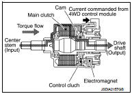
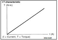
• Transmission torque to the right and left rear wheels is determined according to command current.
Was this page helpful?