Diagnosis System (adas Control Unit 2)
APPLICATION ITEMS
CONSULT performs the following functions via CAN communication using ADAS control unit.
| Diagnosis mode | Description |
|---|---|
| Configuration |
|
| Work support | Displays causes of automatic system cancellation occurred during system control |
| Self Diagnostic Result | Displays the name of a malfunctioning system stored in the ADAS control unit |
| Data Monitor | Displays ADAS control unit input/output data in real time |
| Active Test | Enables an operational check of a load by transmitting a driving signal from the ADAS control unit to the load |
| ECU Identification | Displays ADAS control unit part number |
| CAN Diag Support Monitor | Displays a reception/transmission state of CAN communication and ITS communication |
CONFIGURATION
Configuration includes functions as follows.
| Function | Description | |
|---|---|---|
| Read/Write Configuration | Before Replace ECU | Allows the reading of Nissan Murano vehicle specification written in ADAS control unit to store the specification in CONSULT. |
| After Replace ECU | Allows the writing of the Nissan Murano vehicle information stored in CONSULT into the ADAS control unit. | |
| Manual Configuration | Allows the writing of the Nissan Murano vehicle specification into the ADAS control unit by hand. | |
WORK SUPPORT
| Work support items | Description |
|---|---|
| CAUSE OF AUTO-CANCEL 1 | Displays causes of automatic system cancellation occurred during control of the following systems
|
| CAUSE OF AUTO-CANCEL 4 | Displays causes of automatic braking system cancellation occurred during control of the following systems
|
Display Items for The Cause of Automatic Cancellation 1
| Cause of cancellation | Nissan Murano Vehicle-to-vehicle distance control mode | Conventional (fixed speed) cruise control mode | Automatic Emergency Braking | Description |
| OPERATING ABS | × | × | ABS function was operated | |
| OPERATING TCS | × | × | TCS function was operated | |
| OPERATING VDC | × | × | × | VDC function was operated |
| ECM CIRCUIT | × | × | ECM did not permit ICC operation | |
| OPE SW VOLT CIRC | × | × | The ICC steering switch input voltage is not within standard range | |
| OP SW DOUBLE TOUCH | × | × | ICC steering switches were pressed at the same time | |
| VHCL SPD DOWN | × | × | Nissan Murano Vehicle speed lower than the speed as follows
|
|
| WHL SPD ELEC NOISE | × | × | Wheel speed sensor signal caught electromagnetic noise | |
| VDC/TCS OFF SW | × | × | VDC OFF switch was pressed | |
| VHCL SPD UNMATCH | × | × | Wheel speed became different from CVT Nissan Murano vehicle speed | |
| TIRE SLIP | × | × | Wheel slipped | |
| IGN LOW VOLT | × | × | × | Decrease in ADAS control unit ignition voltage |
| PARKING BRAKE ON | × | × | The parking brake is operating | |
| WHEEL SPD UNMATCH | × | × | The wheel speeds of 4 wheels are out of the specified values | |
| INCHING LOST | × | A Nissan Murano vehicle ahead is not detected during the following driving when the vehicle speed is approximately 24 km/h or less | ||
| CAN COMM ERROR | × | × | × | ADAS control unit received an abnormal signal with CAN communication |
| ABS/TCS/VDC CIRC | × | × | × | An abnormal condition occurs in VDC/TCS/ABS system |
| ECD CIRCUIT | × | × | × | An abnormal condition occurs in ECD system |
| ENG SPEED DOWN | × | × | Engine speed became extremely low while controlling ICC system | |
| ASCD VHCL SPD DTAC | × | Nissan Murano Vehicle speed is detached from set vehicle speed | ||
| ASCD DOUBLE COMD | × | Cancel switch and operation switch are detected simultaneously | ||
| ICC SENSOR CAN COMM ERR | × | × | Communication error between ADAS control unit and the distance sensor (ICC sensor) | |
| ABS WARNING LAMP | × | ABS warning lamp ON | ||
| FR RADAR BLOCKED | × | × | Inclusion of dirt or stains on the distance sensor (ICC sensor) area of the front bumper | |
| FEB) CURVATURE | × | Road curve was more than the specified value | ||
| FEB) YAW RATE | × | Detected yawing speed was more than the specified value | ||
| FEB) LTRL ACCELERATION | × | Detected lateral speed is the specified value or more | ||
| RADAR INTERFERENCE | × | × | Distance sensor (ICC sensor) receives electromagnetic interference | |
| NO RECORD | × | × | — |
Display Items for The Cause of Automatic Cancellation 4
| Cause of cancellation | Description |
| CAN COMM ERROR | ADAS control unit received an abnormal signal with CAN communication |
| VDC OFF SW | VDC OFF switch was pressed |
| ACCEL IS OPERATED 1 | Accelerator pedal was depressed |
| ACCEL IS OPERATED 2 | Accelerator pedal was depressed |
| ECD CIRCUIT | ADAS control unit received and abnormal signal with CAN communication |
| GRADIENT LARGE | Slope, such as uphill, inclination was too steep |
| IGN LOW VOLT | Decrease in ADAS control unit ignition voltage |
| BRAKE IS OPERATED | Brake pedal was operated |
| STEERING ANGLE LARGE | Steering angle was more than the specified value |
| SONAR CIRCUIT | Malfunction of sonar control unit |
| NO RECORD | — |
SELF DIAGNOSTIC RESULT
Refer to DTC Index.
DATA MONITOR
Monitored item [Unit] | ALL SIG (ICC) | MAIN SIG (ICC) | MAIN SIG (LDW/I-LI) | MAIN SIG (BSW/BSI) | Description |
|---|---|---|---|---|---|
MAIN SW [On/Off] |
× | × | × | × | Indicates [On/Off] status as judged from ICC steering switch |
SET/COAST SW [On/Off] |
× | × | Indicates [On/Off] status as judged from ICC steering switch | ||
CANCEL SW [On/Off] |
× | × | Indicates [On/Off] status as judged from ICC steering switch | ||
RESUME/ACC SW [On/Off] |
× | × | Indicates [On/Off] status as judged from ICC steering switch | ||
DISTANCE SW [On/Off] |
× | Indicates [On/Off] status as judged from ICC steering switch | |||
CRUISE OPE [On/Off] |
× | × | Indicates whether controlling or not (ON means “controlling”) | ||
BRAKE SW [On/Off] |
× | × | × | × | Indicates [On/Off] status as judged from brake pedal position switch signal (ECM transmits brake switch signal through CAN communication) |
STOP LAMP SW [On/Off] |
× | × | × | × | Indicates [On/Off] status as judged from stop lamp switch signal (ECM transmits stop lamp switch signal through CAN communication) |
IDLE SW [On/Off] |
× | Indicates [On/Off] status of idle switch read from ADAS control unit through CAN communication (ECM transmits On/Off status through CAN communication) | |||
SET DISTANCE [Short/Mid/Long] |
× | × | Indicates set distance memorized in ADAS control unit | ||
CRUISE LAMP [On/Off] |
× | × | Indicates [On/Off] status of MAIN switch indicator output | ||
OWN VHCL [On/Off] |
× | Indicates [On/Off] status of own Nissan Murano vehicle indicator output | |||
VHCL AHEAD [On/Off] |
× | Indicates [On/Off] status of Nissan Murano vehicle ahead detection indicator output | |||
ICC WARNING [On/Off] |
× | Indicates [On/Off] status of ICC system warning lamp output | |||
VHCL SPEED SE [km/h] or [mph] |
× | × | × | × | Indicates Nissan Murano vehicle speed calculated from ADAS control unit through CAN communication [ABS actuator and electric unit (control unit) transmits Nissan Murano vehicle speed signal (wheel speed) through CAN communication] |
SET VHCL SPD [km/h] or [mph] |
× | × | Indicates set Nissan Murano vehicle speed memorized in ADAS control unit | ||
BUZZER O/P [On/Off] |
× | Indicates [On/Off] status of ICC warning chime output | |||
THRTL SENSOR [deg] |
× | × | |||
ENGINE RPM [rpm] |
× | Indicates engine speed read from ADAS control unit through CAN communication (ECM transmits engine speed signal through CAN communication) | |||
WIPER SW [OFF/LOW/HIGH] |
× | Indicates wiper [OFF/LOW/HIGH] status (BCM transmits front wiper request signal through CAN communication) | |||
BA WARNING [On/Off] |
× | Indicates [On/Off] status of AEB indicator lamp output | |||
STP LMP DRIVE [On/Off] |
× | × | Indicates [On/Off] status of brake hold drive signal | ||
D RANGE SW [On/Off] |
× | Indicates [On/Off] status of “D” or “M” positions read from ADAS control unit through CAN communication; ON when position “D” or “M” (TCM transmits shift position signal through CAN communication). | |||
NP SW SIG [On/Off] |
× | × | Indicates [On/Off] status as judged from park/neutral position switch signal (ECM transmits park/neutral position switch signal through CAN communication) | ||
SL MAIN SW [On/Off] |
× | × | Indicates [On/Off] status as judged from steering switch | ||
PKB SW [On/Off] |
× | Parking brake switch status [On/Off] judged from the parking brake switch signal that ADAS control unit readout via CAN communication is displayed (combination meter transmits the parking brake switch signal via CAN communication) | |||
PWR SUP MONI [V] |
× | × | Indicates IGN voltage input by ADAS control unit | ||
THRTL OPENING [%] |
× | x | x | Indicates throttle position read from ADAS control unit through CAN communication (ECM transmits accelerator pedal position signal through CAN communication). | |
GEAR [1, 2, 3, 4, 5, 6, 7] |
× | x | Indicates CVT gear position read from ADAS control unit through CAN communication (TCM transmits current gear position signal through CAN communication) | ||
MODE SIG [OFF, ICC, ASCD] |
× | Indicates the active mode from ICC or ASCD [conventional (fixed speed) cruise control mode] | |||
SET DISP IND [On/Off] |
× | Indicates [On/Off] status of SET switch indicator output | |||
DYNA ASIST SW [On/Off] |
× | × | Indicates [On/Off] status as judged from ICC steering switch signal (ECM transmits ICC steering switch signal through CAN communication) | ||
LDW SYSTEM ON [On/Off] |
× | Indicates [On/Off] status of LDW system | |||
LDW ON INDICATOR [On/Off] |
Indicates [On/Off] status of LDW system display output | ||||
LDP ON IND [On/Off] |
× | Indicates [On/Off] status of I-LI system display output | |||
LDP SYSTEM ON [On/Off] |
× | Indicates [On/Off] status of I-LI system | |||
LANE DPRT W/L [On/Off] |
x | × | Indicates [On/Off] status of LDWI-LI warning display (Yellow) output | ||
STATUS signal [Stnby/Warn/Cancl/Off] |
× | Indicates a control state of I-LI system | |||
CAMERA LOST [Detect/Deviate/Both] |
x | × | Indicates a lane marker detection state judged from a lane marker detection signal read by the ADAS control unit via ITS communication (Lane camera unit transmits a lane marker signal via ITS communication) |
||
SIDE G [G] |
x | × | × | Indicates lateral G acting on the Nissan Murano vehicle. This lateral G is judged from a side G sensor signal read by ADAS control unit via CAN communication (The ABS actuator and electric unit (control unit) transmits a side G sensor signal via CAN communication) |
|
ITS SETTING ITEM(LDP) [On/Off] |
x | × | × | Indicates the presence or absence of I-LI system. | |
ITS SETTING ITEM(BSW) [On/Off] |
x | × | Indicates the presence or absence of BSW system. | ||
Turn signal [OFF/LH/RH/LH&RH] |
× | × | Indicates turn signal operation status read from ADAS control unit through CAN communication (BCM transmits turn indicator signal through CAN communication) | ||
LDP SELECT [On/Off] |
× | × | × | × | Indicates an ON/OFF state of I-LI system. I-LI system can be set to ON/OFF by selecting “Driving Aids”⇒“Lane” in the combination meter |
LDW SELECT [On/Off] |
× | × | × | × | Indicates an ON/OFF state of the LDW system. The LDW system can be set to ON/OFF by selecting “Driving Aids”⇒“Lane” of the integral switch |
BSW SELECT [On/Off] |
× | × | × | × | Indicates an ON/OFF state of the BSW system. The BSW system can be set to ON/OFF by selecting “Driving Aids”⇒“Blind spot” of the integral switch |
BSW SYSTEM ON [On/Off] |
× | × | Indicates [On/Off] status of BSW system | ||
BSW/BSI WARN LMP [On/Off] |
× | Indicates [On/Off] status of Blind Spot warning malfunction | |||
BATTERY CIRCUIT OFF [On/Off] |
|||||
LDP WARNING INDICATOR [On/Off] |
× | Indicates [On/Off] status of I-LI warning display (Yellow) output | |||
LDW ON INDICATOR [On/Off] |
× | Indicates [On/Off] status of LDW system ON display output | |||
LDW WARNING INDICATOR [On/Off] |
× | Indicates [On/Off] status of LDW system warning display output | |||
ITS SETTING ITEM(LDP) [On/Off] |
× | × | × | × | Indicates the presence or absence of I-LI system. |
| ITS SETTING ITEM (BSI) | × | × | × | × | Indicates the presence or absence of Blind Spot Intervention system. |
BSW ON INDICATOR [On/Off] |
× | Indicates [On/Off] status of BSW system ON display output | |||
FUNC ITEM(FEB) [On/Off] |
Indicates systems which can be set to ON/OFF by selecting “Driver Assistance”⇒“Emergency Brake” of the combination meter | ||||
FEB SELECT [On/Off] |
Indicates an ON/OFF state of the AEB system. The AEB system can be set to ON/OFF by selecting “Driver Assistance”⇒“Emergency Brake” of the combination meter | ||||
FEB SW [On/Off] |
|||||
FEB SW OPE [On/Off] |
× | ||||
FEB SW IND [On/Off] |
× | ||||
RAB warning lamp (operation) [on/off] |
Indicates [On/Off] status of RAB system warning indicator. | ||||
RAB warning lamp (malf) [on/off] |
Indicates [On/Off] status of RAB system warning light. |
ACTIVE TEST
| Test item | Description |
|---|---|
| STOP LAMP | The brake hold drive signal can be operated by ON/OFF operations as necessary, and the stop lamp can be illuminated |
| ICC BUZZER | Sounds a buzzer used for following systems by arbitrarily operating ON/OFF
|
| BRAKE ACTUATOR | Activates the brake by an arbitrary operation |
| LDP BUZZER | Sounds a buzzer used for following systems by arbitrarily operating ON/OFF
|
| LDP ON IND | The I-LI system display can be illuminated by ON/OFF operations as necessary |
| LANE DEPARTURE W/L | The LDW/I-LI warning can be illuminated by ON/OFF operations as necessary |
| BSW WARNING LAMP | The Blind Spot Warning system display can be illuminated by ON/OFF operations as necessary |
| BSW ON INDICATOR | The Blind Spot Warning system display can be illuminated by ON/OFF operations as necessary |
| LDW ON INDICATOR | The LDW system display can be illuminated by ON/OFF operations as necessary |
| LDP WARNING INDICATOR | The I-LI malfunction can be illuminated by ON/OFF operations as necessary |
| LDW WARNING INDICATOR | The LDW malfunction can be illuminated by ON/OFF operations as necessary |
| Vibration motor | The steering vibration motor can be operated ON/OFF |
| RAB warning lamp (operation) | The RAB system display can be illuminated by ON/OFF operations as necessary |
| RAB warning lamp (malfunction) | The RAB malfunction can be illuminated by ON/OFF operations as necessary |
| ADAS buzzer 2 | Sounds a buzzer used for following systems by arbitrarily operating ON/OFF
|
STOP LAMP
| Test item | Operation | Description | Stop lamp |
|---|---|---|---|
| STOP LAMP | Off | Stops transmitting the brake hold drive signal to end the test | OFF |
| On | Transmits the brake hold drive signal | ON |
ICC BUZZER
| Test item | Operation | Description | Operation sound |
|---|---|---|---|
| ICC BUZZER | MODE1 | Transmits the buzzer output signals to the ADAS control unit via ITS communication | Intermittent beep sound |
| Test start | Starts the tests of “MODE1” | — | |
| Reset | Stops transmitting the buzzer output signal to end the test | — | |
| End | Returns to the “SELECT TEST ITEM” screen | — |
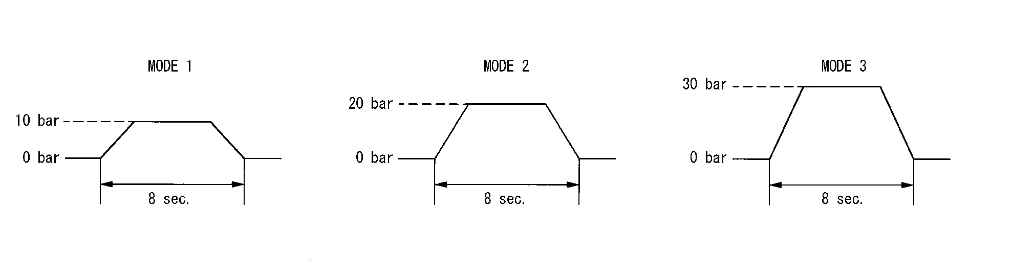
BRAKE ACTUATOR
| Test item | Operation | Description | “PRESS SENS” value |
|---|---|---|---|
| BRAKE ACTUATOR | MODE1 | Transmits the brake fluid pressure control signal to the ABS actuator and electric unit (control unit) via CAN communication | 10 bar |
| MODE2 | 20 bar | ||
| MODE3 | 30 bar | ||
| Test start | Starts the tests of “MODE1”, “MODE2” and “MODE3” | — | |
| Reset | Stops transmitting the brake fluid pressure control signal to end the test | — | |
| End | Returns to the “SELECT TEST ITEM” screen | — |
LDP BUZZER
| Test item | Operation | Description | Warning buzzer |
|---|---|---|---|
| LDP BUZZER | Off | Stops transmitting the warning buzzer signal to end the test | — |
| On | Transmits the warning buzzer signal to the warning system buzzer | ON |
LDP ON IND
| Test item | Operation | Description | I-LI system display (Green) |
|---|---|---|---|
| LDP ON IND | Off | Stops transmitting the meter display signal to end the test | — |
| On | Transmits the meter display signal to the combination meter via CAN communication | ON |
LANE DEPARTURE W/L
| Test item | Operation | Description | Lane departure system display (Yellow) |
|---|---|---|---|
| LANE DEPARTURE W/L | Off | Stops transmitting the meter display signal to end the test | — |
| On | Transmits the meter display signal to the combination meter via CAN communication | ON |
BSW ON LAMP
| Test item | Operation | Description | Lane departure system display (Yellow) |
|---|---|---|---|
| BSW ON INDICATOR | Off | Stops transmitting the meter display signal below to end the test | — |
| On | Transmits the meter display signal to the combination meter via CAN communication | ON |
LDW ON INDICATOR
| Test item | Operation | Description | LDW system display (White) |
|---|---|---|---|
| LDW ON INDICATOR | Off | Stops transmitting the meter display signal to end the test | — |
| On | Transmits the meter display signal to the combination meter via CAN communication | ON |
LDP WARNING INDICATOR
| Test item | Operation | Description | I-LI malfunction (Yellow) |
|---|---|---|---|
| LDP WARNING INDICATOR | Off | Stops transmitting the meter display signal to end the test | — |
| On | Transmits the meter display signal to the combination meter via CAN communication | ON |
LDW WARNING INDICATOR
| Test item | Operation | Description | LDW malfunction (Yellow) |
|---|---|---|---|
| LDW WARNING INDICATOR | Off | Stops transmitting the meter display signal to end the test | — |
| On | Transmits the meter display signal to the combination meter via CAN communication | ON |
VIBRATION MOTOR
| Test item | Operation | Description | Vibration motor |
|---|---|---|---|
| Vibration motor | Off | Stops sending the steering vibration motor signal to end the test | OFF |
| On | Transmits the steering vibration motor signal | ON |
RAB WARNING LAMP (OPERATION)
| Test item | Operation | Description | RAB system warning light |
|---|---|---|---|
| RAB warning lamp (operation) | Off | Stops transmitting the meter display signal below to end the test | — |
| On | Transmits the meter display signal to the combination meter via CAN communication | ON |
RAB WARNING LAMP (MALFUNCTION)
| Test item | Operation | Description | RAB system warning indicator |
|---|---|---|---|
| RAB warning lamp (malfunction) | Off | Stops transmitting the meter display signal below to end the test | — |
| On | Transmits the meter display signal to the combination meter via CAN communication | ON |
ADAS BUZZER 2
| Test item | Operation | Description | Warning buzzer |
|---|---|---|---|
| ADAS buzzer 2 | Off | Stops transmitting the warning buzzer signal to end the test | — |
| On | Transmits the warning buzzer signal to the warning system buzzer | ON |
ECU IDENTIFICATION
Displays ADAS control unit parts number.