Diagnosis System (combination Meter)
COMBINATION METER SELF-DIAGNOSIS MODE
The following meter functions can be checked during Combination Meter Self-Diagnosis Mode:
Pointer sweep of speedometer, tachometer and gauges
Illumination of all LCD segments and color patterns for meter displays
Illumination of all lamps/LEDs that are controlled by the combination meter (regardless of switch status)
STARTING COMBINATION METER SELF-DIAGNOSIS MODE
How to Initiate Self-Diagnosis Mode
Ignition switch OFF.
While pressing the trip reset switch (1), place ignition switch ON.
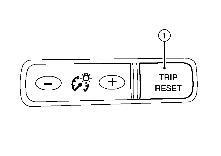
Keep pressing the trip reset switch for 1 second or more.
Press the trip reset switch at least 3 times within 7 seconds after the ignition switch is placed ON.
“Work instruction code” is indicated in the top portion of information display and self-diagnosis is started.
The mode switches in the order shown below each time the trip reset switch is pressed.
| Test order | Test item | Description | |
|---|---|---|---|
| 1 | Work instruction code | This item is displayed, but not used. | |
| 2 | Part number | ||
| 3 | Software code | ||
| 4 | EEPROM code | ||
| 5 | Hardware code | ||
| 6 | P.C.B code | ||
| 7 | Circuit check | The pointer of the following items moves from 0 to MAX twice.
|
|
| 8 | Color check | Performs the color check of the information display. | |
| 9 | Error code | Displays the error code of the following items:
|
|
| 10 | Warning/indicator lamp check | All warning/indicator lamps illuminate. | |
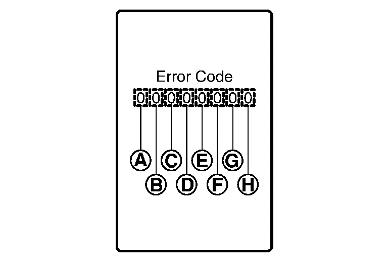
| Item | Code | Description | Action to take/Reference | |
|---|---|---|---|---|
 |
Speedometer | 0 | Normal | — |
| 1 | A Nissan Murano vehicle speed signal cannot be received from ABS actuator and electric unit (control unit). | Select "Self Diagnostic Result" mode of “ABS”. Refer to DTC Index. |
||
| 2 | A Nissan Murano vehicle speed signal received from the ABS actuator and electric unit (control unit) is abnormal. | |||
 |
Tachometer | 0 | Normal | — |
| 1 | An engine speed signal cannot be received from ECM. | Select "Self Diagnostic Result" mode of “ENGINE”. Refer to DTC Index. |
||
 |
Fuel gauge | 0 | Normal | — |
| 1 | Fuel gauge circuit is shorted. | Refer to Component Function Check. | ||
| 2 | Fuel gauge circuit is open. | |||
 |
Engine coolant temperature gauge | 0 | Normal | — |
| 1 | An engine coolant temperature signal cannot be received from ECM. | Select "Self Diagnostic Result" mode of “ENGINE”. Refer to DTC Index. |
||
 |
Meter control switch | 0 | Normal | — |
| 1 | When judging that the illumination control switch signal circuit is shorted for 5 minutes or more. | Refer to Diagnosis Procedure. | ||
| 2 | When judging that the trip reset switch signal circuit is shorted for 5 minutes or more. | |||
| 3 | When judging that both switch signal circuit are shorted for 5 minutes or more. | |||
 |
— | 0 | Displays “0” constantly. | — |
 |
— | 0 | Displays “0” constantly. | — |
 |
— | 0 | Displays “0” constantly. | — |
How to Reset Error Code
Error codes stored in combination meter can be reset by following the instructions below:
Ignition switch OFF.
While pressing the trip reset switch, place ignition switch ON.
Keep pressing the trip reset switch for 1 second or more.
Press the trip reset switch at least 3 times within 7 seconds after the ignition switch is placed ON.
Ignition switch OFF.
Perform self-diagnosis and check that the error codes are reset.
APPLICATION ITEMS
CONSULT can display each diagnostic item using the diagnostic test modes shown.
| METER/M&A Diagnosis mode | Description | |
|---|---|---|
| Self Diagnostic Result | Displays combination meter self-diagnosis results. | |
| Data Monitor | Displays combination meter input/output data in real time. | |
| Work support | Displays diagnosis procedure of each work item. | |
| ECU Identification | Displays combination meter part number. | |
| Warning History | Lighting history of the warning lamp and indicator lamp can be checked. | |
| CAN DIAG SUPPORT MNTR | The result of transmit/receive diagnosis of CAN communication can be read. | |
SELF DIAG RESULT
Refer to DTC Index.
DATA MONITOR
Display Item List
X: Applicable
| Display item [Unit] | MAIN SIGNALS | Description |
|---|---|---|
SPEED METER [mph or km/h] |
X | Displays the value of Nissan Murano vehicle speed signal. |
SPEED OUTPUT [mph or km/h] |
X | Nissan Murano Vehicle speed signal value transmitted to other units via CAN communication. |
ODO OUTPUT [mph or km/h] |
Odometer signal value transmitted to other units via CAN communication. | |
TACHO METER [rpm] |
X | Value of the engine speed signal received from ECM via CAN communication. |
FUEL METER [L] |
X | Fuel level indicated on combination meter. |
W TEMP METER [°F] or [°C] |
X | Displays the value of engine coolant temperature signal, which is input from ECM. |
ABS W/L [On/Off] |
Displays [ON/OFF] condition of ABS warning indicator. | |
VDC/TCS IND [On/Off] |
Displays [ON/OFF] condition of VDC OFF indicator lamp. | |
SLIP IND [On/Off] |
Displays [ON/OFF] condition of SLIP indicator lamp. | |
BRAKE W/L [On/Off] |
Displays [ON/OFF] condition of brake warning indicator. | |
DOOR W/L [On/Off] |
Displays [ON/OFF] condition of door open warning message. | |
TRUNK/GLAS-H [On/Off] |
Displays [ON/OFF] condition of back door open warning message. | |
HI-BEAM IND [On/Off] |
Displays [ON/OFF] condition of high beam indicator. | |
TURN IND [On/Off] |
Displays [ON/OFF] condition of turn indicator. | |
LIGHT IND [On/Off] |
Displays [ON/OFF] condition of light indicator. | |
FR FOG IND [On/Off] |
Displays [ON/OFF] condition of front fog lamp indicator. | |
OIL W/L [On/Off] |
Displays [ON/OFF] condition of low oil pressure warning message in the information display. | |
MIL [On/Off] |
Displays [ON/OFF] condition of malfunction indicator. | |
BA W/L [On/Off] |
Displays [ON/OFF] condition of AEB warning lamp indicator. | |
ATC/T-AMT W/L [On/Off] |
Displays [ON/OFF] condition of CVT check warning message in the information display. | |
4WD W/L [On/Off] |
Displays [ON/OFF] condition of AWD warning message in the information display. | |
FUEL W/L [On/Off] |
Displays [ON/OFF] condition of low-fuel warning message in the information display. | |
WASHER W/L [On/Off] |
Displays [ON/OFF] condition of low washer fluid warning message in the information display. | |
AIR PRES W/L [On/Off] |
Displays [ON/OFF] condition of tire pressure warning lamp. | |
KEY G/Y W/L [On/Off] |
Displays [ON/OFF] condition of key green warning lamp. | |
EPS W/L [On/Off] |
Displays [ON/OFF] condition of EPS warning indicator. | |
| LCD | X | Displays the value of Intelligent Key system message indication. |
ACC TARGET [On/Off] |
Displays [ON/OFF] condition of Nissan Murano vehicle ahead detection indicator in the information display. | |
ACC DISTANCE [Off, Short, Middle, Long] |
Displays [Off, Short, Middle, Long] condition of set distance indicator in the information display. | |
SHIFT IND [P, R, N, D] |
Displays shift selector position. | |
FUEL CAP W/L [On/Off] |
Displays [ON/OFF] condition of loose fuel cap warning message in the information display. | |
M RANGE SW [On/Off] |
Status of manual mode switch. | |
NM RANGE SW [On/Off] |
Status of non-manual mode switch. | |
AT SFT UP SW [On/Off] |
Status of manual mode shift up switch. | |
AT SFT DWN SW [On/Off] |
Status of manual mode shift down switch. | |
PKB SW [On/Off] |
Displays [ON/OFF] condition of parking brake switch. | |
BUCKLE SW [On/Off] |
Displays [ON/OFF] condition of seat belt buckle switch LH. | |
BRAKE OIL SW [On/Off] |
Displays [ON/OFF] condition of brake fluid level switch. | |
DISTANCE [Mi] or [km] |
Displays distance to empty. | |
OUTSIDE TEMP [°F or °C] |
Displays the ambient air temperature which is input from the ambient sensor. | |
FUEL LOW SIG [On/Off] |
Displays [ON/OFF] condition of low-fuel warning signal. | |
STRG SW INPUT [SW 1-SW 10, NOT INPUT] |
Displays [SW 1-SW 10, NOT INPUT] condition of steering switches. | |
SONAR DET STATUS [On/Off] |
Displays [ON/OFF] condition of sonar detection area. | |
SONAR WARN [Off, SENSOR DEACTIVE, SENSOR ERROR] |
Displays [OFF, SENSOR DEACTIVE, SENSOR ERROR] condition of sonar warning. | |
SONAR DET DSP RC [On/Off] |
Displays [ON/OFF] condition of RC sonar detection display. | |
SONAR DET DSP AREA RC [On/Off] |
Displays [ON/OFF] condition of RC sonar detection area image. | |
SONAR DET DSP RL [On/Off] |
Displays [ON/OFF] condition of RL sonar detection display. | |
SONAR DET DSP AREA RL [On/Off] |
Displays [ON/OFF] condition of RL sonar detection area image. | |
SONAR DET DSP RR [On/Off] |
Displays [ON/OFF] condition of RR sonar detection display. | |
SONAR DET DSP AREA RR [On/Off] |
Displays [ON/OFF] condition of RR sonar detection area image. | |
SONAR DET DSP FC [On/Off] |
Displays [ON/OFF] condition of FC sonar detection display. | |
SONAR DET DSP AREA FC [On/Off] |
Displays [ON/OFF] condition of FC sonar detection area image. | |
SONAR DET DSP FL [On/Off] |
Displays [ON/OFF] condition of FL sonar detection display. | |
SONAR DET DSP AREA FL [On/Off] |
Displays [ON/OFF] condition of FL sonar detection area image. | |
SONAR DET DSP FR [On/Off] |
Displays [ON/OFF] condition of FR sonar detection display. | |
SONAR DET DSP AREA FR [On/Off] |
Displays [ON/OFF] condition of FR sonar detection area image. | |
SONAR DIST DSP [On/Off] |
Displays sonar distance status. | |
BUZZER [On/Off] |
X | Buzzer status (in the combination meter) is detected from the buzzer output signal received from each unit via CAN communication and the warning output condition of the combination meter. |
TPMS PRESS L [On/Off] |
Displays [ON/OFF] condition of tire pressure low message in the information display. | |
4WD CL TMP H [On/Off] |
Displays [ON/OFF] condition of AWD system warning (AWD high temp) detected from AWD warning display error signal is received from AWD control unit via CAN communication. | |
4WD TIRE CHCK [On/Off] |
Displays [ON/OFF] condition of AWD system warning (tire size incorrect) detected from AWD warning display error signal is received from AWD control unit via CAN communication. | |
4WD SYS MALF [On/Off] |
Displays [ON/OFF] condition of AWD system warning (AWD error) detected from AWD warning display error signal is received from AWD control unit via CAN communication. | |
ASCD SPD BLNK [On/Off] |
Blinking status of ASCD set Nissan Murano vehicle speed judged by the ASCD status signal received from ECM via CAN communication. | |
ASCD STATUS [Off, ASCD, CRUISE] |
Status of ASCD status display judged by the ASCD status signal received from ECM via CAN communication. | |
ASCD REQ SPD [km/h/Off] |
ASCD set Nissan Murano vehicle speed value judged by the ASCD status signal received from ECM via CAN communication. | |
TPMS DISP [Not suport, HIGH, MEDIUM, LOW] |
Status of tire pressure low from tire pressure data signal is received from BCM via CAN communication. | |
TIRE STATUS FR [On/Off] |
Status of tire pressure data signal (front RH) from BCM via CAN communication. | |
TIRE STATUS FL [On/Off] |
Status of tire pressure data signal (front LH) from BCM via CAN communication. | |
TIRE STATUS RR [On/Off] |
Status of tire pressure data signal (rear RH) from BCM via CAN communication. | |
TIRE STATUS RL [On/Off] |
Status of tire pressure data signal (rear LH) from BCM via CAN communication. | |
LDW IND [On/Off] |
Status of LDW system display detected from meter display signal is received from ADAS control unit via CAN communication. | |
SET LDW [On/Off/Not support] |
Status of LDW system setting. | |
SET BSW [On/Off/Not support] |
Status of BSW system setting. | |
TIRE PRESS FR [kPa, kg/cm2 or Psi] |
The data of front RH tire pressure from BCM via CAN communication. | |
TIRE PRESS FL [kPa, kg/cm2 or Psi] |
The data of front LH tire pressure from BCM via CAN communication. | |
TIRE PRESS RR [kPa, kg/cm2 or Psi] |
The data of rear RH tire pressure from BCM via CAN communication. | |
TIRE PRESS RL [kPa, kg/cm2 or Psi] |
The data of rear LH tire pressure from BCM via CAN communication. | |
BSW IND [On/Off] |
Displays [ON/OFF] condition of blind spot warning indicator. | |
LDP IND [On/Off] |
Displays [Off, Short, Middle, Long] status of set distance indicator in the information display. | |
HI-BEAM ASST IND [mph/Off] |
Displays [ON/OFF] condition of high beam assist indicator lamp from high beam assist indicator lamp signal is received from BCM via CAN communication. |
WORK SUPPORT
| Work support item | Description |
|---|---|
| Outside air temperature diagnosis | A possible malfunction can be narrowed down by following the displayed instructions. |
| Fuel meter diagnosis(Analog pointer) | |
| Warning lamp diagnosis |
ECU IDENTIFICATION
Combination meter part number can be read.
Special menu
| Display item | Description |
|---|---|
| W/L ON HISTORY | Lighting history of warning lamp and indicator lamp can be checked. |
W/L ON HISTORY
“W/L ON HISTORY” indicates the “TIME” when the warning/indicator lamp is turned on.
The “TIME” above is:
0: The condition that the warning/indicator lamp has been turned on 1 or more times after starting the engine and waiting for 30 seconds.
1 - 39: The number of times the engine was restarted after the 0 condition.
NO W/L ON HISTORY: No warning/indicator lamp history is stored.