Fwd
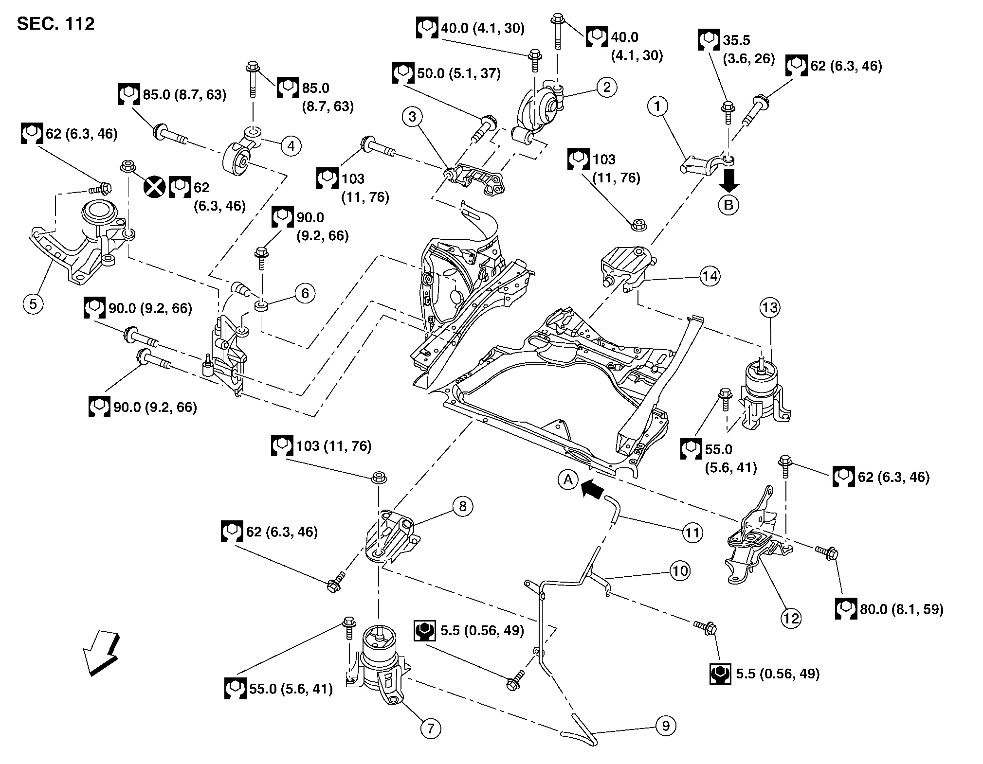
| 1. | Gusset | 2. | Rear torque rod | 3. | Rear torque rod bracket |
| 4. | Upper torque rod | 5. | Engine mounting insulator (RH) | 6. | Engine mounting bracket (RH) |
| 7. | Engine mounting insulator (front) | 8. | Engine mounting bracket (front) | 9. | Vacuum hose |
| 10. | Vacuum tube (front) | 11. | Vacuum hose | 12. | Engine mounting insulator (LH) |
| 13. | Engine mounting insulator (rear) | 14. | Engine mounting bracket (rear) | 15. | Engine mounting stay (rear) |
| A. | To electronic controlled engine mount control solenoid valve. Refer to Exploded View. | B. | To transmission. Refer to Exploded View. |  |
Front |
REMOVAL
Outline
Remove the engine and transmission with the front suspension member as a unit. Separate the engine from the transmission and remove from the front suspension member.
Preparation
Release fuel pressure. Refer to Work Procedure.
Drain engine coolant. Refer to Changing Engine Coolant.
Remove the front under cover. Refer to Removal and Installation.
Remove the front wheels and tires using power tool. Refer to Removal and Installation.
Remove the fender protector (LH/RH), Refer to Removal and Installation.
Engine Room
Remove cowl top and cowl top extension. Refer to Exploded View.
Remove the air duct (inlet), air cleaner cases (upper and lower) with mass air flow sensor and air duct assembly. Refer to Exploded View.
Remove the engine room cover. Refer to Removal and Installation.
Drain the power steering fluid. Refer to Draining and Refilling.
Disconnect engine room harness at the CVT and ECM connectors.
Remove the battery tray. Refer to Removal and Installation.
Disconnect heater hoses (engine side). Refer to Removal and Installation.
Remove upper and lower radiator hoses. Refer to Exploded View.
Remove high pressure pipe, low pressure pipe, high pressure flexible hose, and low pressure flexible hose. Refer to Exploded View.
Remove EVAP hose.
Disconnect fuel feed hose quick connector at fuel tube side. Refer to Exploded View.
Disconnect CVT control cable. Refer to Exploded View.
Disconnect brake booster vacuum hose at brake booster. Refer to Exploded View.
Remove harness ground cable.
Disconnect low pressure hose from steering pump. Refer to Removal and Installation.
Disconnect high pressure piping from steering pump. Refer to Removal and Installation.
Disconnect the wiring harness from the distribution/fuse block.
Disconnect the CVT fluid cooler hoses from the CVT.
Remove the upper RH upper torque rod.
Remove engine mounting insulator (RH) three upper nuts.
Vehicle Underbody
Remove exhaust front tube. Refer to Exploded View.
Disconnect steering lower joint at power steering gear assembly and release steering lower shaft. Refer to Exploded View.
Disconnect front stabilizer connecting rod. Refer to Exploded View.
Remove front brake caliper assembles with piping connected and position them aside. Refer to Removal and Installation.
Remove rear plate cover from oil pan (upper). Then remove nuts attaching the drive plate to the torque converter. Refer to Dowel Pin Alignment.
Remove crankshaft position sensor (POS). Refer to Exploded View.
Removal
Use suitable tool to securely support bottom of front suspension member.
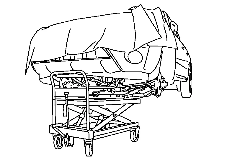
Remove front suspension member mounting nuts and bolts. Refer to Exploded View.
Carefully lower table to remove the engine, the transmission and the front suspension member. When performing work, observe the following caution:
Separation
Install engine slingers into front of cylinder head (bank 1) and rear of cylinder head (bank 2).
Type 1
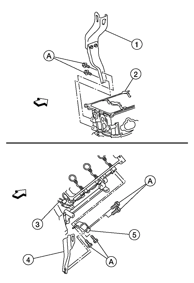
| (1) | : Engine rear slinger |
| (2) | : cylinder head (bank 2) |
| (3) | : cylinder head (bank 1) |
| (4) | : Engine front slinger (upper) |
| (5) | : Engine front slinger (lower) |
|
: Engine front |
| Bolts (A) | : 28 N·m |
Type 2
(A): Cylinder head (bank 1)
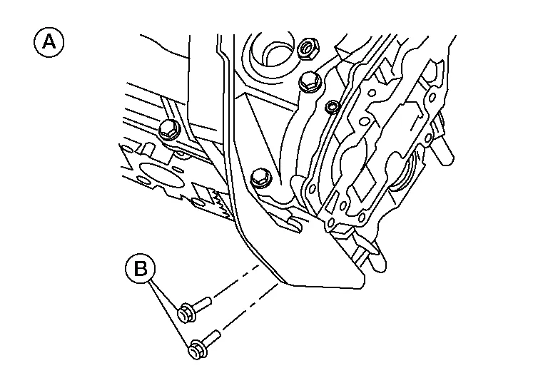
| Bolts (B) | : 28 N·m |
(B): Cylinder head (bank 2)
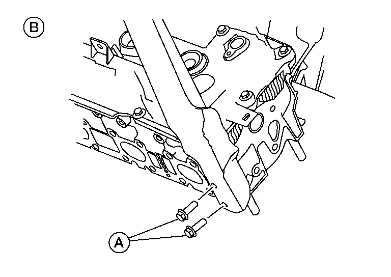
| Bolts (A) | : 28 N·m |
Disconnect vacuum hose from front engine mounting insulator.
Remove CVT fluid level indicator and CVT charging pipe. Refer to Exploded View.
Remove starter. Refer to Removal and Installation.
Remove front drive shaft (LH/RH). Refer to Removal and Installation (LH) and Removal and Installation (RH).
Remove coolant reservoir.
Remove engine mounting insulator (rear).
Disconnect CVT unit harness connector from CVT.
Remove transmission to engine bolts. Refer to Exploded View.
Separate engine and transmission assembly. Refer to Removal and Installation.
Lift the engine from the front suspension member.
INSTALLATION
Installation is in the reverse order of removal.
INSPECTION AFTER INSTALLATION
Before starting engine, check oil/fluid levels including engine coolant and engine oil. If there is less than required quantity, fill to the specified level. Refer to Fluids and Lubricants.
Use procedure below to check for fuel leakage.
Turn ignition switch ON (with engine stopped). With fuel pressure applied to fuel piping, check for fuel leakage at connection points.
Start engine. With engine speed increased, check again for fuel leakage at connection points.
Run engine to check for unusual noise and vibration.
Warm up engine thoroughly to make sure there is no leakage of fuel, exhaust gas, or any oils/fluids including engine oil and engine coolant.
Bleed air from passages in lines and hoses, such as in cooling system.
After cooling down engine, again check oil/fluid levels including engine oil and engine coolant. Refill to specified level, if necessary.
Summary of the inspection items:
Item Before starting engine Engine running After engine stopped Engine coolant Level Leakage Level Engine oil Level Leakage Level Transmission/transaxle fluid A/T and CVT Models Leakage Level/Leakage Leakage M/T Models Level/Leakage Leakage Level/Leakage Other oils and fluids* Level Leakage Level Fuel Leakage Leakage Leakage Exhaust gas — Leakage — *Power steering fluid, brake fluid, etc.