Body Exterior, Doors, Roof & Vehicle Security
Main Power Window and Door Lock/unlock Switch
In this manual: Body Exterior, Doors, Roof & Vehicle Security
~3min read
TERMINAL LAYOUT

PHYSICAL VALUES
Terminal No. (wire color) | Description | Condition | Voltage (Approx.) | ||
|---|---|---|---|---|---|
| + | - | Signal name | Input/Output | ||
1 (B) |
Ground | Ground | Output | — | 0 |
4 (R) |
12 (Y) |
Encoder pulse signal 2 | Input | When power window motor operates | 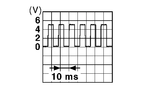 |
5 (Y) |
12 (Y) |
Encoder pulse signal 1 | Input | When power window motor operates | |
6 (L) |
Ground | Rear power window motor RH DOWN signal. | Output | When rear power window switch RH is operated DOWN | Battery voltage |
7 (V) |
Ground | Rear power window motor RH UP signal. | Output | When rear power window switch RH is operated UP | Battery voltage |
8 (LG) |
Ground | Rear power window motor LH DOWN signal. | Output | When rear power window switch LH is operated DOWN | Battery voltage |
9 (SB) |
Ground | Rear power window motor LH UP signal. | Output | When rear power window switch LH is operated UP | Battery voltage |
10 (BR) |
Ground | Ignition switch power supply | Input | Ignition switch ON | Battery voltage |
| Other than above | 0 | ||||
11 (Y/L) |
Ground | Power window serial link | Input/Output | IGN SW ON or power window operating. | 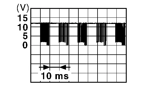 |
12 (Y) |
Ground | Encoder ground | — | — | 0 |
14 (P) |
Ground | Encoder power supply | Output | When ignition is ON or power window timer operates. | Battery voltage |
17 (G) |
19 (Y) |
Main power window and door lock/unlock switch UP signal | Output | When main power window and door lock/unlock switch is operated UP | Battery voltage |
18 (Y) |
Ground | Battery power supply | Input | — | Battery voltage |
19 (Y) |
17 (G) |
Main power window and door lock/unlock switch DOWN signal | Output | When main power window and door lock/unlock switch is operated DOWN | Battery voltage |
FAIL-SAFE CONTROL
Switches to fail-safe control when malfunction is detected in encoder signal that detects up/down speed and direction of door glass. Switches to fail-safe control when an error beyond the regulation value is detected between the fully closed position and the actual position of the glass.
| Malfunction | Malfunction condition |
|---|---|
| Pulse sensor malfunction | When only one side of pulse signal is being detected for more than the specified value. |
| Both pulse sensors malfunction | When both pulse signals have not been detected for more than the specified value during glass open/close operation. |
| Pulse direction malfunction | When the pulse signal that is detected during glass open/close operation detects the opposite condition of power window motor operating direction. |
| Glass recognition position malfunction 1 | When it detects the error between glass fully closed position in power window switch memory and actual fully closed position during glass open/close operation is more than the specified value. |
| Glass recognition position malfunction 2 | When it detects pulse count more that the value of glass full stroke during glass open/close operation. |
| Malfunction of not yet updated closed position of glass | When glass open/close operation is continuously performed without fully closing more that the specified value (approximately 10 strokes). |
It changes to condition before initialization and the following functions do not operate when switched to fail-safe control:
Auto-up operation
Anti-pinch function
Retained power function
Perform initial operation to recover when switched to fail-safe mode. However, it switches back to fail-safe control when malfunction is found in power window switch or in motor.
Was this page helpful?