Transverse Link

| 1. | Transverse link | 2. | Front suspension member |
REMOVAL
Remove steering knuckle with wheel hub and bearing. Refer to Removal and Installation.
Remove transverse link nuts and bolts from suspension member.
Remove transverse link from suspension member.
INSPECTION AFTER REMOVAL
TRANSVERSE LINK
Transverse link for deformation, cracks or damage.
Bushing for complete separation. (If completely separated, inner metal can be pulled out from transverse link.)
Bushing for leakage.
Ball joint boot for cracks or other damage, and also for grease leakage.
Swinging Torque Inspection
Move ball joint at least ten times by hand to check for smooth movement.
Hook Tool (A) on ball joint at pinch bolt location. Confirm measurement value is within specifications when ball joint begins moving.
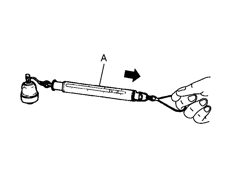
Tool number : – (J-44372) Swinging torque : Refer to Ball Joint. If swinging torque exceeds standard range, replace transverse link.
Rotating Torque Inspection
Move ball joint at least ten times by hand to check for smooth movement.
Confirm measurement value is within specifications when ball joint begins rotating.
Rotating torque : Refer to Ball Joint. If rotating torque exceeds standard range, replace transverse link.
Axial End Play Inspection
Move ball joint at least ten times by hand to check for smooth movement.
Move tip of ball joint in axial direction to check for looseness.
If there is axial end play, replace transverse link assembly.
INSTALLATION
Installation is in reverse order of removal.
Perform final tightening of bolts and nuts at front suspension member under unladen conditions with tires on level ground.
Check wheel alignment. Refer to Inspection.
Adjust neutral position of steering angle sensor. Refer to Description.