Description
To improve vehicle performance, more and more ECUs take into account more and more various information, in order to always approach optimal operation.
With multiplexing, the information supplied by a single sensor can be used by several ECUs, thereby reducing the length of wiring and the number of sensors.
I - SOLUTION WITHOUT MULTIPLEXING
Example: to use the vehicle speed information, each ECU would need its own electrical link with the wheel anti-lock sensor.
II - SOLUTION WITH MULTIPLEXING
Engine speed is distributed to the ECUs by a single link.
III - ADVANTAGES OF MULTIPLEXING
- Lower costs through reduced wire length and fewer connectors.
- Reduced wiring weight.
- Increased reliability due to fewer wires and connectors.
- Easier isolation of a faulty component in some cases.
IV - HOW DOES IT WORK?
Take the example of a metro line carrying many passengers. The passengers, even if they are not going to the same places, use the same metro line and pass through, or get off at, the same stations while being carried by trains. Some stations may see a large number of passengers getting on and off, without changing the track of the line compared with less busy stations.
The exchange of information on the multiplexed network (data BUS) works somewhat like a metro line.
This information, once formatted as frames, is sent to each of the ECUs:
- 1: An ECU formats a piece of information (from a sensor or an internal calculation) into a "frame" so that the nature of the information is identified by the other ECUs.
- 2: Once the information is formatted, the control unit waits for the bus to be free, meaning no message is being transmitted. Unlike the metro, the signal injected onto the multiplex network travels in both directions from the transmitting control unit, so the line must be clear to prevent messages from mixing.
- 3: The control unit transmits the information on the multiplex network once the line is clear.
- 4: The message travels on the multiplex network and reaches all connected control units. Unlike metro passengers, it does not "get off" the line. It travels to the ends of the network. Each control unit reads the information passing on the multiplex network and recognises the information intended for it thanks to the formatting applied by the transmitting control unit.
Exchanges on the multiplex network therefore have several advantages: - the same information can be received by several control units at once and simultaneously, - if a control unit does not correctly interpret the information intended for it, it can force the transmitter to repeat the frame concerned by sending an information request message on the bus.
V - WHAT DOES THE "DATA BUS" LOOK LIKE?
It consists of two copper electrical wires, most often twisted together. The two wires operate as a differential pair, which provides better immunity to electronic interference and limits radiation.
The two wires are called Can_H and Can_L.
For a metro train to run smoothly on its track, the rail spacing must be almost continuous. The same applies to signals travelling on the bus: they must be of good quality. For this reason, "terminating resistors" are added at each end of the bus (engine control unit and body control unit). These terminating resistors, also called "matching resistors", are equal to 120 Ω in order to smooth the signals (absorb harmful interference). For this reason, the data bus cannot be repaired: a splice would degrade the impedance.
VI - WHAT DOES THE SIGNAL LOOK LIKE?
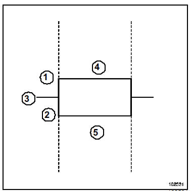
- Can_H
- Can_L
- 2,5 V
- 3,5 V
- 1,5 V
The two electrical wires that make up the bus are called Can_H and Can_L. Digital signals travel on these wires. Information is transmitted as square-wave signals on a differential pair, which provides better immunity to electromagnetic interference and limits radiation. The signals on the wires are strictly opposite: 2.5 to 3.5 V on the Can_H line and 2.5 to 1.5 V on the Can_L line.
VII - THE CAN PROTOCOL
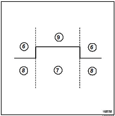
- Recessive
- Dominant
- 0 V
- 2 V
differential voltage between Can_H and Can_L. If it is above a certain threshold, the corresponding logic level is dominant (bit* value = 0). Otherwise, it is recessive (bit* value = 1).
* : A bit is the unit state, represented in binary form as 0 or 1, of a digital signal.
VIII - THE CAN FRAME
It formats information so that it can be used by a control unit that reads from the bus. It is a message made up of several combined parts, including:
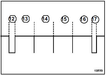
- A field indicating the start of a CAN frame
- An arbitration field indicating the recipient control unit(s) (and the priority of access to the network when several control units want to transmit)
- A control field helping to secure the transmission
- A field containing the message data
- An acknowledgement field indicating that the frame has been correctly received on the network
- A CAN frame end field
IX - SPECIAL CASES
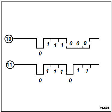
If several control units attempt to transmit a frame at the same time, the frame with the lowest arbitration field has priority. The lowest arbitration field is the one that stays dominant the longest or sends a dominant bit "0" the fastest.
A bit is the unit state of a digital signal, represented in binary form as 0 or 1.
Example: frame (10) has priority over frame (11).
If a message is corrupted or incorrectly received by a control unit, the acknowledgement field will not be validated and the message is discarded by the control units. The message is automatically retransmitted until it is validated.
X - DIAGNOSTICS
Multiplex control units fitted with a diagnostic link include multiplex network diagnostics.
Each control unit monitors its ability to transmit and the regular arrival of messages from other control units. Any anomaly detected results in one or more faults, either present or stored, on the multiplex network. These faults are grouped in a format common to all control units, in a frame dedicated to multiplex network diagnostics.
In the aftermarket, these faults can be viewed with diagnostic tools in order to identify the faulty inter-control unit link(s) and determine the nature and location of the fault.
Each time a diagnostic tool is connected to the vehicle, a "multiplex network test" is performed by the tool.
XI - REPAIRING THE MULTIPLEX NETWORK
The multiplex link is established on all concerned control units by means of splices in the harness.
Diagnosing the bus consists of checking:
- continuity line by line,
- insulation from earth and from voltage,
- line impedance:
- 60 Ω between Can_H and Can_L (battery disconnected, between pins 6 and 14 of the diagnostic socket),
- 120 Ω between Can_H and Can_L on the airbag control unit side (disconnected from the network),
- 120 Ω between Can_H and Can_L on the engine injection control unit side (disconnected from the network),
- frames can be viewed with an oscilloscope.
Do not use crimp terminals or solder the multiplex network. To repair it, the harness must be replaced.
XII - OPERATING DIAGRAM
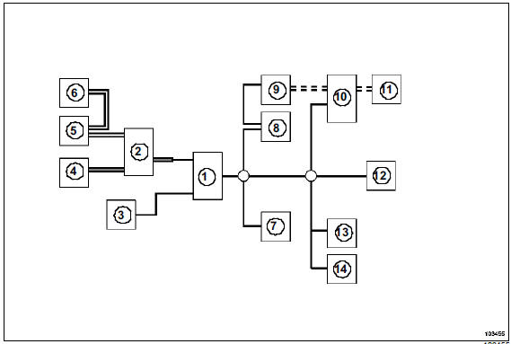
- Body control unit
- Protection and communication unit
- Electric steering column lock
- Anti-lock braking system (ABS)
- Injection
- Automatic transmission
- Diagnostic socket
- Electric power steering
- Instrument panel
- High-end navigation
- High-end radio
- Airbags and belt tensioners
- Air conditioning
- Driving school box
==== : Engine multiplexed link
____ : Passenger compartment multiplexed link
= = = : Multimedia multiplexed link
Test yourself
A quick Renault Megane quiz: every answer comes with an explanation and a link to the manual page.