Rear Differential Lock Control Switch
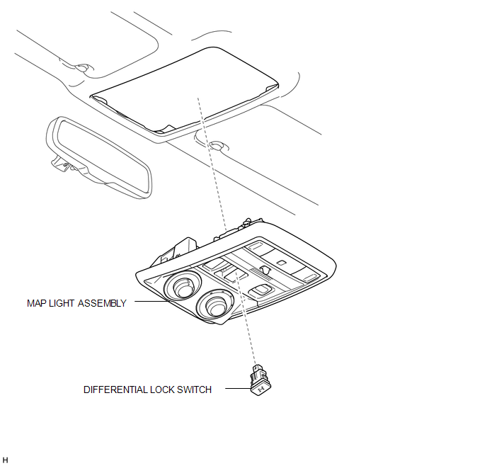
Inspection INSPECTION PROCEDURE
1. INSPECT DIFFERENTIAL LOCK SWITCH
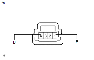
(a) Measure the resistance according to the value(s) in the table below.
Standard Resistance:
Tester Connection | Switch Condition | Specified Condition |
|---|---|---|
1 (E) - 4 (B) |
Pressed |
Below 1 Ω |
Not pressed |
100 kΩ or higher |
*a |
Component without harness connected (Differential Lock Switch) |
If the result is not as specified, replace the differential lock switch.
Removal REMOVAL PROCEDURE1. REMOVE MAP LIGHT ASSEMBLY

2. REMOVE DIFFERENTIAL LOCK SWITCH
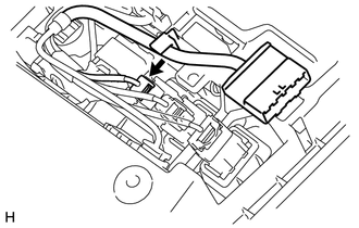
(a) Disconnect the differential lock switch connector. |
 |
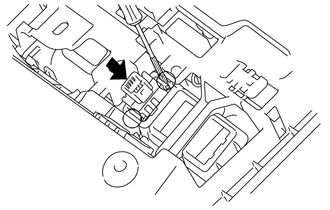
(b) Using a screwdriver, detach the 2 claws and remove the differential lock switch from the map light assembly. HINT: Tape the screwdriver tip before use. |
 |
1. INSTALL DIFFERENTIAL LOCK SWITCH
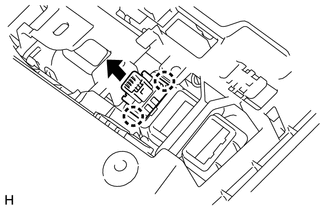
(a) Attach the 2 claws to install the differential lock switch to the map light assembly. |
 |
(b) Connect the connector.
2. INSTALL MAP LIGHT ASSEMBLY

Test yourself
A quick Toyota 4Runner quiz: every answer comes with an explanation and a link to the manual page.