Antenna Cable
Components
COMPONENTS
ILLUSTRATION
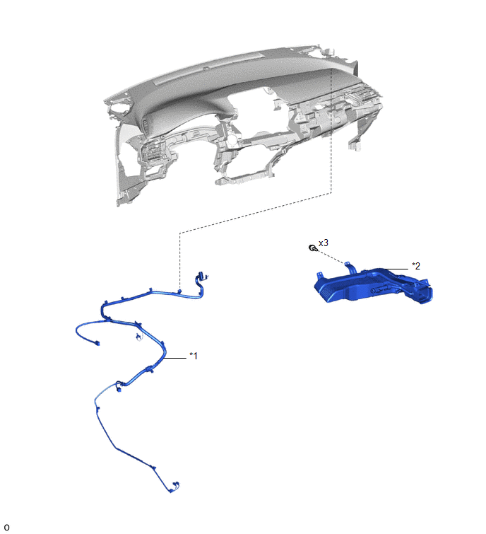
*1 |
ANTENNA CABLE SUB-ASSEMBLY |
*2 |
HEATER DAMPER DUCT SUB-ASSEMBLY NO. 3 |
ILLUSTRATION
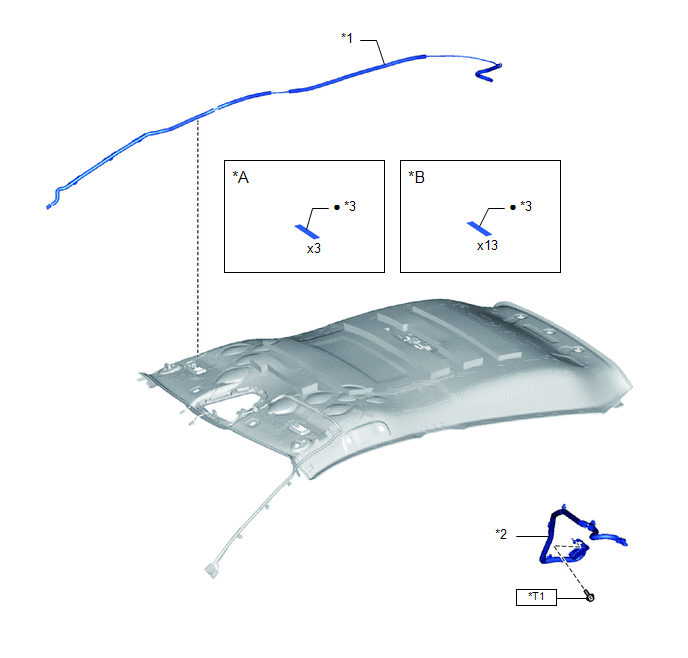
*A |
Type A |
*B |
Type B |
*1 |
ANTENNA CABLE SUB-ASSEMBLY NO. 2 |
*2 |
ANTENNA CABLE SUB-ASSEMBLY NO. 3 |
*3 |
ADHESIVE TAPE |
- |
- |
● |
Non-reusable part |
- |
- |
*T1 |
for type A: 10.5 N*m (107 kgf*cm, 8 ft*lbf) for type B: 10 N*m (102 kgf*cm, 7 ft*lbf) for type C: 10 N*m (102 kgf*cm, 7 ft*lbf) |
- |
- |
Removal
REMOVAL
PRECAUTION / NOTICE / HINT
The procedures required (adjustment, calibration, initialization or registration) that must be performed after parts have been removed and installed or replaced during removal/installation of the antenna cable assembly are shown below.
Procedures Required After Replacement / Removal / Installation of PartsReplaced Part or Performed Procedure | Required Procedure | Effect/Inoperative Function When Required Procedure Is Not Performed | Link |
|---|---|---|---|
Disconnect the cable from the negative (-) battery terminal. |
Initialize Back Door Lock |
Door Lock Control System |
 |
Memorize Steering Angle Neutral Point |
Lane Departure Alert System (with Steering Control) |
|
|
Pre-Collision System |
CAUTION:
Some service operations affect the SRS airbag system. Before starting any service operation, carefully read the precautions for the SRS airbag system.
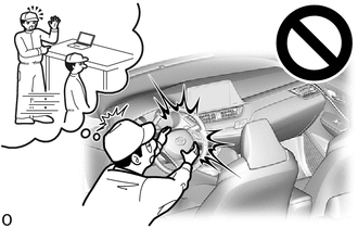
Click here
PROCEDURE
1. REMOVE ANTENNA CABLE SUB-ASSEMBLY
Click here
Installation
INSTALLATION
PROCEDURE
1. INSTALL ANTENNA CABLE SUB-ASSEMBLY
Click here