Brake System (Other)
Brake Line
In this manual: Brake System (Other)
~3min read
Precautions
PRECAUTION
PRECAUTION FOR TROUBLESHOOTING
NOTICE:
- As brake lines are critical safety parts, remove and inspect all component parts if brake fluid leaks. If any abnormality is found, replace the component part with a new one.
- When removing brake system components, cover the brake line connections to prevent foreign matter (dust or dirt) from entering the lines.
- Do not damage or deform the brake lines during removal and installation procedures.
- When installing a grommet on the vehicle body, make sure the brake line passes through the center of the washer.
- When installing a brake line or hose, make sure it is not twisted or tangled.
- If the metal end of a hose does not align properly with the groove in the bracket, twist the hose slightly to insert it.
- Hoses must not show any traces of shock absorber oil, grease, etc.
- When installing a brake line on a plastic clip, make sure the brake line is not loose or pinched.
- Do not reuse clips or plastic clips that have been removed from a hose.
- After installing a brake line or hose, make sure it does not interfere with other components or the body.
- Do not allow brake fluid to spill onto a painted body surface. If brake fluid leaks onto a painted surface, clean it immediately.
- When disconnecting and reconnecting a hose and brake line:
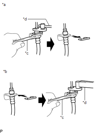
*a
Disconnection
*b
Connection
*c
Hold
*d
Turn
- Hold the hose with a wrench, and disconnect the brake line with a flare nut wrench without deforming it.
- Remove the clip and disconnect the hose.
- Secure the hose with a new clip. At this stage, be sure to install the clip correctly.
- Connect the brake line with a flare nut wrench without deforming it.
- When connecting a brake line and clip:
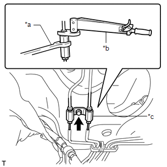
*a
Hold
*b
Turn
*c
Clip
- Hold the clip to prevent deformation of the brake line, and connect the brake line to the clip using a flare nut wrench.
- Hold the clip to prevent deformation of the brake line, and install the bolt to secure the clip to the body.
System Diagram
SYSTEM DIAGRAM
HINT:
Refer to the diagram to check the locations and torque specifications of the hoses and brake lines.
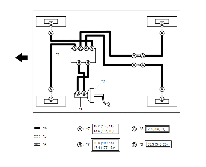
*1 |
Brake Actuator Assembly |
*2 |
Brake Booster Assembly |
*3 |
Brake Master Cylinder Sub-assembly |
*4 |
Brake Tube |
*5 |
Hose |
*6 |
Brake Tube Clip |
*7 |
Flare Nut |
*8 |
Union Bolt |
 |
Torque for "Main Areas Related to Basic Vehicle Performance" such as Driving/Turning/Stopping: N*m (kgf*cm, lbf*ft) |
* |
Use with flare nut wrench |
 |
FRONT |
- |
- |
Was this page helpful?