Vehicle Lifting And Supporting Points
VEHICLE LIFTING AND SUPPORTING POINTS
NOTICE REGARDING VEHICLE CONDITION WHEN LIFTING THE VEHICLE
(a) The vehicle must be empty when jacking up or lifting the vehicle. Never lift or jack up the vehicle when it is carrying a heavy load.
(b) When removing heavy components such as the engine or transaxle, the center of gravity of the vehicle will shift. To stabilize the vehicle, place a counterweight in a position that will prevent the vehicle from moving or shifting, or place a transmission jack in the appropriate position at the opposite end of the vehicle.
NOTICE REGARDING USE OF A FOUR-POST LIFT
(a) Follow the safety procedures described in the lift operator's manual.
(b) Take care not to damage the tires or wheels when driving the vehicle onto the lift.
(c) Use wheel chocks to secure the vehicle.
NOTICE REGARDING USE OF A JACK AND SAFETY STANDS
(a) Work on a flat surface. Always use wheel chocks.
(b) Use safety stands with rubber pads, as shown in the illustration.
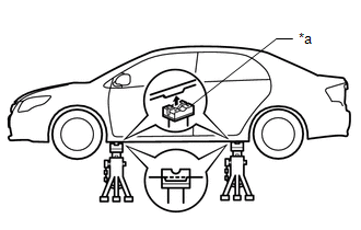
*a |
Rubber pad |
(c) Install the jack and safety stands exactly at the specified locations on the vehicle.
Never place the jack or safety stands under suspension parts, such as the front lower arm, when jacking up the vehicle.
(d) Do not work under a vehicle supported only by a jack, and do not leave a vehicle supported only by a jack. Make sure the vehicle is also supported on safety stands.
(e) When raising the vehicle with a jack, first release the parking brake, place the shift lever in N, and make sure the neutral (N) position has been selected.
(f) When raising the entire vehicle:
(1) When jacking up the front wheels, make sure wheel chocks are placed behind the rear wheels.
(2) When jacking up the rear wheels, make sure wheel chocks are placed in front of the front wheels.
(g) When jacking up the front or rear wheels of the vehicle:
(1) Before jacking up the front wheels, place wheel chocks on both sides of the rear wheels.
(2) Before jacking up the rear wheels, place wheel chocks on both sides of the front wheels.
(h) When lowering a vehicle where only the front or rear wheels are raised on a jack.
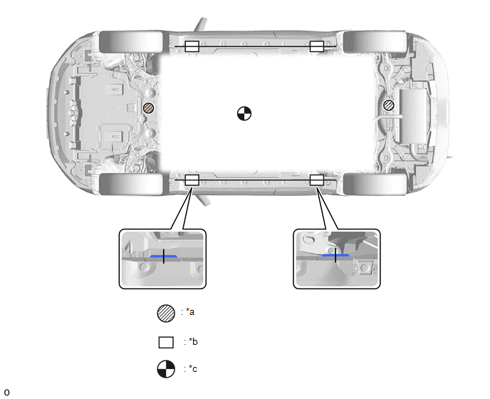
*a |
JACK LOCATION |
*b |
SUPPORT POINT - Safety stand - Swing arm type lift - Beam type lift |
*c |
VEHICLE CENTER OF GRAVITY (unladen) |
- |
- |
(1) Before lowering the front wheels of the vehicle, make sure wheel chocks are placed in front of the rear wheels.
(2) Before lowering the rear wheels of the vehicle, make sure wheel chocks are placed behind the front wheels.
NOTE ON USING A SWING ARM TYPE LIFT
(a) Follow the safety procedures described in the lift operator's manual.
(b) Use swing arms with rubber pads, as shown in the illustration.
(c) Position the vehicle so that its center of gravity is centered on the lift (the length of the "L" shown in the illustration should be as short as possible).
(d) Make sure the rubber pads or swing arms do not contact the underbody panels or lower body moldings.
(e) Be sure to lock the swing arms (if equipped with a locking device) before lifting.
(f) Using the lift, raise the vehicle until the tires are no longer touching the floor, then stop and rock the front and rear of the vehicle to make sure it is stable.
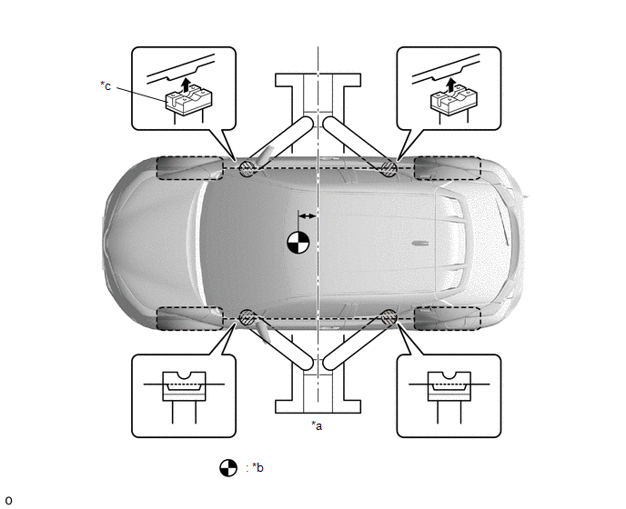
*a |
Center of lift |
*b |
VEHICLE CENTER OF GRAVITY (unladen) |
*c |
Rubber pad |
- |
- |
NOTE ON USING A BEAM TYPE LIFT
(a) Follow the safety procedures described in the lift operator's manual.
(b) Use beam lift attachments (rubber lift blocks) on top of the beams.
(c) Be sure to position the vehicle at the specified location, described in the following table and shown in the following illustration.
Left and right position adjustment |
Center the vehicle on the lift. |
Front and rear position adjustment |
|
(d) Make sure the beam type lift or rubber lift blocks do not contact the underbody panels or lower body moldings.
(e) Using the lift, raise the vehicle until the tires are no longer touching the floor, then stop and rock the front and rear of the vehicle to make sure it is stable.
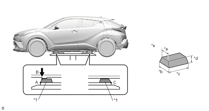
*1 |
Attachment |
- |
- |
*a |
85 mm (3.35 in) |
*b |
100 mm (3.94 in) |
*c |
200 mm (7.87 in) |
*d |
70 mm (2.76 in) |
*e |
Attachment dimensions |
- |
- |