Inspection
INSPECTION
PROCEDURE
1. INSPECT OUTSIDE REAR VIEW MIRROR SWITCH ASSEMBLY (without Power Folding Mirror)
(a) Inspect the mirror surface select and adjustment switch.
(1) Set the mirror surface select and adjustment switch to the L position. |
|
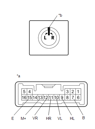
(2) Measure the resistance according to the value(s) shown in the table below.
Standard resistance (Left side):
Tester Connection | Condition | Specified Condition |
|---|---|---|
10 (VL) - 7 (B) 13 (M+) - 15 (E) |
Up |
Below 1 Ω |
OFF |
10 kΩ minimum |
|
10 (VL) - 15 (E) 13 (M+) - 7 (B) |
Down |
Below 1 Ω |
OFF |
10 kΩ minimum |
|
9 (HL) - 7 (B) 13 (M+) - 15 (E) |
Left |
Below 1 Ω |
OFF |
10 kΩ minimum |
|
9 (HL) - 15 (E) 13 (M+) - 7 (B) |
Right |
Below 1 Ω |
OFF |
10 kΩ minimum |
(3) Set the mirror surface select and adjustment switch to the R position.
(4) Measure the resistance according to the value(s) shown in the table below.
Standard resistance (Right side):
Tester Connection | Condition | Specified Condition |
|---|---|---|
12 (VR) - 7 (B) 13 (M+) - 15 (E) |
Up |
Below 1 Ω |
OFF |
10 kΩ minimum |
|
12 (VR) - 15 (E) 13 (M+) - 7 (B) |
Down |
Below 1 Ω |
OFF |
10 kΩ minimum |
|
11 (HR) - 7 (B) 13 (M+) - 15 (E) |
Left |
Below 1 Ω |
OFF |
10 kΩ minimum |
|
11 (HR) - 15 (E) 13 (M+) - 7 (B) |
Right |
Below 1 Ω |
OFF |
10 kΩ minimum |
If the result is not as specified, replace the outside rear view mirror switch assembly.
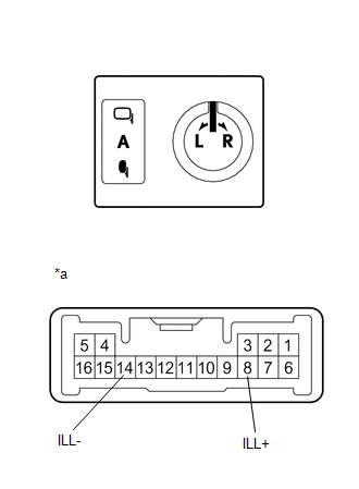
(b) Check that the LED lights up. (1) Apply battery voltage to the outside rear view mirror switch assembly and check that the LED lights up. OK:
If the result is not as specified, replace the outside rear view mirror switch assembly. |
|
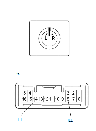
2. INSPECT OUTSIDE REAR VIEW MIRROR SWITCH ASSEMBLY (with Power Folding Mirror)
(a) Inspect the mirror surface select and adjustment switch.
(1) Set the mirror surface select and adjustment switch to the L position. |
|
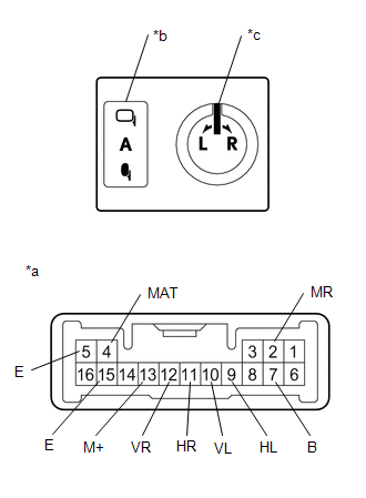
(2) Measure the resistance according to the value(s) shown in the table below.
Standard resistance (Left side):
Tester Connection | Condition | Specified Condition |
|---|---|---|
10 (VL) - 7 (B) 13 (M+) - 15 (E) |
Up |
Below 1 Ω |
OFF |
10 kΩ minimum |
|
10 (VL) - 15 (E) 13 (M+) - 7 (B) |
Down |
Below 1 Ω |
OFF |
10 kΩ minimum |
|
9 (HL) - 7 (B) 13 (M+) - 15 (E) |
Left |
Below 1 Ω |
OFF |
10 kΩ minimum |
|
9 (HL) - 15 (E) 13 (M+) - 7 (B) |
Right |
Below 1 Ω |
OFF |
10 kΩ minimum |
(3) Set the mirror surface select and adjustment switch to the R position.
(4) Measure the resistance according to the value(s) shown in the table below.
Standard resistance (Right side):
Tester Connection | Condition | Specified Condition |
|---|---|---|
12 (VR) - 7 (B) 13 (M+) - 15 (E) |
Up |
Below 1 Ω |
OFF |
10 kΩ minimum |
|
12 (VR) - 15 (E) 13 (M+) - 7 (B) |
Down |
Below 1 Ω |
OFF |
10 kΩ minimum |
|
11 (HR) - 7 (B) 13 (M+) - 15 (E) |
Left |
Below 1 Ω |
OFF |
10 kΩ minimum |
|
11 (HR) - 15 (E) 13 (M+) - 7 (B) |
Right |
Below 1 Ω |
OFF |
10 kΩ minimum |
(5) Inspect the mirror folding switch.
(6) Measure the resistance according to the value(s) shown in the table below.
Standard resistance:
Tester Connection | Condition | Specified Condition |
|---|---|---|
4 (MAT) - 5 (E) |
AUTO position |
Below 1 Ω |
Any position other than AUTO |
10 kΩ minimum |
|
2 (MR) - 5 (E) |
Folding position: |
Below 1 Ω |
Except folded position |
10 kΩ minimum |
If the result is not as specified, replace the outside rear view mirror switch assembly.
(b) Check that the LED lights up. (1) Apply battery voltage to the outside rear view mirror switch assembly and check that the LED lights up. OK:
If the result is not as specified, replace the outside rear view mirror switch assembly. |
|