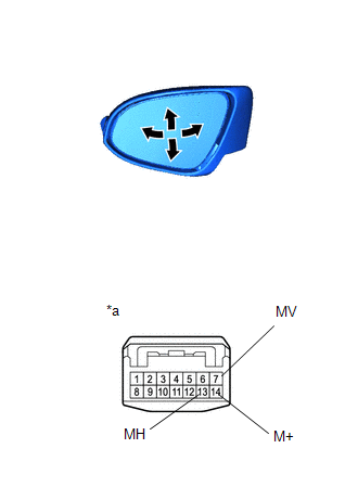
(1) Apply voltage and check the operation of the left outer mirror assembly.
OK:
Battery connection
Specified Condition
Battery positive (+) → Terminal 7 (MV)
Battery negative (-) → Terminal 14 (M+)
Tilts up
Battery positive (+) → Terminal 14 (+) (M+)
Battery negative (-) → Terminal 7 (MV)
Tilts down
Battery positive (+) → Terminal 13 (MH)
Battery negative (-) → Terminal 14 (M+)
Turns right
Battery positive (+) → Terminal 14 (+) (M+)
Battery negative (-) → Terminal 13 (MH)
Turns left
If the result is not as specified, replace the left outer mirror assembly.
*a
Component without wire harness connected
(Left outer mirror assembly)
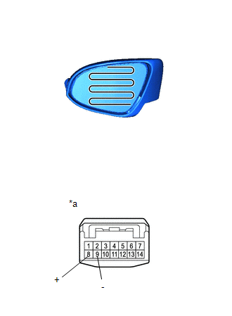
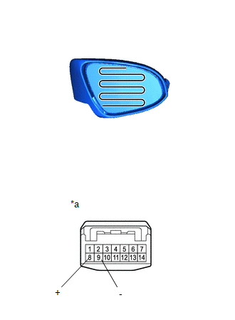
(b) Check the operation of the heated mirror.
(1) Measure the resistance according to the value(s) shown in the table below.
Standard resistance:
Tester Connection
Condition
Specified Condition
8 (+) - 9 (-)
25 °C
8,5 à 11,5 Ω
If the result is not as specified, inspect the left outer mirror.
(2) Connect one wire from the battery positive (+) terminal to terminal 8 and the wire from the battery negative (-) terminal to terminal 9, then check that the mirror heats up.
HINT:
The mirror takes a long time to heat up.
OK:
The mirror heats up.
If the result is not as specified, inspect the left outer mirror.
*a
Component without wire harness connected
(Left outer mirror assembly)
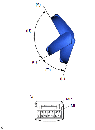
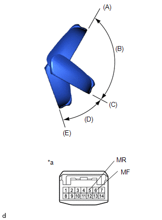
(c) Check the operation of the folding mirror. (with power folding mirror)
NOTICE:
Disconnect and reconnect the battery between checks of each mirror position.
The mirror position cannot be changed manually while the battery is connected. Disconnect the battery first to change the mirror position manually.
If the motor remains powered after each mirror position check, the motor may malfunction. Be sure to disconnect the battery immediately after performing each mirror position check.
(1) Disconnect the connector from the left outer mirror assembly.
(2) For each position: Disconnect the battery, adjust the mirror position manually, reconnect the battery, and check the movement of the folding mirror.
OK:
Battery connection
Condition
Specified Condition
Battery positive (+) → Terminal 5 (MR)
Battery negative (-) → Terminal 6 (MF)
Forward position (A)
Moves from (A) to (E)
Battery positive (+) → Terminal 6 (MF)
Battery negative (-) → Terminal 5 (MR)
Forward position (A)
Does not move
Battery positive (+) → Terminal 5 (MR)
Battery negative (-) → Terminal 6 (MF)
Position between forward position (A) and driving position (C)
Moves from (B) to (E)
Battery positive (+) → Terminal 6 (MF)
Battery negative (-) → Terminal 5 (MR)
Position between forward position (A) and driving position (C)
Moves from (B) to (A)
Battery positive (+) → Terminal 5 (MR)
Battery negative (-) → Terminal 6 (MF)
Driving position (C)
Moves from (C) to (E)
Battery positive (+) → Terminal 6 (MF)
Battery negative (-) → Terminal 5 (MR)
Driving position (C)
Does not move
Battery positive (+) → Terminal 5 (MR)
Battery negative (-) → Terminal 6 (MF)
Position between driving position (C) and folded position (E)
Moves from (D) to (E)
Battery positive (+) → Terminal 6 (MF)
Battery negative (-) → Terminal 5 (MR)
Position between driving position (C) and folded position (E)
Moves from (D) to (C)
Battery positive (+) → Terminal 5 (MR)
Battery negative (-) → Terminal 6 (MF)
Folded position (E)
Does not move
Battery positive (+) → Terminal 6 (MF)
Battery negative (-) → Terminal 5 (MR)
Folded position (E)
Moves from (E) to (C)
If the result is not as specified, replace the left outer mirror assembly.
*a
Component without wire harness connected
(Left outer mirror assembly)
2. INSPECT RIGHT OUTER MIRROR ASSEMBLY
(a) Check the operation of the mirror surface.
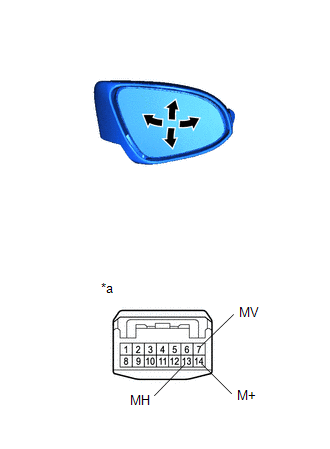
(1) Apply voltage and check the operation of the right outer mirror assembly.
OK:
Battery connection
Specified Condition
Battery positive (+) → Terminal 7 (MV)
Battery negative (-) → Terminal 14 (M+)
Tilts up
Battery positive (+) → Terminal 14 (+) (M+)
Battery negative (-) → Terminal 7 (MV)
Tilts down
Battery positive (+) → Terminal 13 (MH)
Battery negative (-) → Terminal 14 (M+)
Turns left
Battery positive (+) → Terminal 14 (+) (M+)
Battery negative (-) → Terminal 13 (MH)
Turns right
If the result is not as specified, replace the right outer mirror assembly.
*a
Component without wire harness connected
(Right outer mirror assembly)
(b) Check the operation of the heated mirror.
(1) Measure the resistance according to the value(s) shown in the table below.
Standard resistance:
Tester Connection
Condition
Specified Condition
8 (+) - 9 (-)
25 °C
8,5 à 11,5 Ω
If the result is not as specified, inspect the right outer mirror.
(2) Connect one wire from the battery positive (+) terminal to terminal 8 and the wire from the battery negative (-) terminal to terminal 9, then check that the mirror heats up.
HINT:
The mirror takes a long time to heat up.
OK:
The mirror heats up.
If the result is not as specified, inspect the right outer mirror.
*a
Component without wire harness connected
(Right outer mirror assembly)
(c) Check the operation of the folding mirror. (with power folding mirror)
NOTICE:
Disconnect and reconnect the battery between checks of each mirror position.
The mirror position cannot be changed manually while the battery is connected. Disconnect the battery first to change the mirror position manually.
If the motor remains powered after each mirror position check, the motor may malfunction. Be sure to disconnect the battery immediately after performing each mirror position check.
(1) Disconnect the connector from the right outer mirror assembly.
(2) For each position: Disconnect the battery, adjust the mirror position manually, reconnect the battery, and check the movement of the folding mirror.
OK:
Battery connection
Condition
Specified Condition
Battery positive (+) → Terminal 5 (MR)
Battery negative (-) → Terminal 6 (MF)
Forward position (A)
Moves from (A) to (E)
Battery positive (+) → Terminal 6 (MF)
Battery negative (-) → Terminal 5 (MR)
Forward position (A)
Does not move
Battery positive (+) → Terminal 5 (MR)
Battery negative (-) → Terminal 6 (MF)
Position between forward position (A) and driving position (C)
Moves from (B) to (E)
Battery positive (+) → Terminal 6 (MF)
Battery negative (-) → Terminal 5 (MR)
Position between forward position (A) and driving position (C)
Moves from (B) to (A)
Battery positive (+) → Terminal 5 (MR)
Battery negative (-) → Terminal 6 (MF)
Driving position (C)
Moves from (C) to (E)
Battery positive (+) → Terminal 6 (MF)
Battery negative (-) → Terminal 5 (MR)
Driving position (C)
Does not move
Battery positive (+) → Terminal 5 (MR)
Battery negative (-) → Terminal 6 (MF)
Position between driving position (C) and folded position (E)
Moves from (D) to (E)
Battery positive (+) → Terminal 6 (MF)
Battery negative (-) → Terminal 5 (MR)
Position between driving position (C) and folded position (E)
Moves from (D) to (C)
Battery positive (+) → Terminal 5 (MR)
Battery negative (-) → Terminal 6 (MF)
Folded position (E)
Does not move
Battery positive (+) → Terminal 6 (MF)
Battery negative (-) → Terminal 5 (MR)
Folded position (E)
Moves from (E) to (C)
If the result is not as specified, replace the right outer mirror assembly.