Removal
REMOVAL
NOTICE:
To prevent the key from being locked in the vehicle, make sure to enter e-latch inspection mode and enable the manual release handle before disconnecting the cable from the negative (-) auxiliary battery terminal.
Click here 
HINT:
When the cable is disconnected / reconnected to the auxiliary battery terminal, systems temporarily stop operating. However, each system has a function that completes learning the first time the system is used.
Items for which learning is completed by driving the vehicleEffect/Inoperative Function when Necessary Procedure not Performed | Necessary Procedure | Link |
|---|---|---|
Front Camera System |
Drive the vehicle straight ahead at 15 km/h or more for 5 seconds or more. |
|
Effect/Inoperative Function when Necessary Procedure not Performed | Necessary Procedure | Link |
|---|---|---|
Power door lock control system
|
Perform door unlock operation with door control switch or electrical key transmitter sub-assembly switch. |
|
Power Back Door System |
Reset back door close position |
|
Air Conditioning System |
After the ignition switch is turned to ON, the servo motor standard position is recognized. |
- |
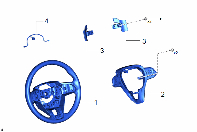
Procedure | Part Name Code |  |  |  |
|
|---|---|---|---|---|---|
1 |
STEERING WHEEL ASSEMBLY |
45100 |
- |
- |
- |
2 |
STEERING PAD SWITCH ASSEMBLY |
84250A |
- |
- |
- |
3 |
SHIFT PADDLE SWITCH (TRANSMISSION SHIFT SWITCH ASSEMBLY) |
- |
- |
- |
- |
4 |
NO. 1 SWITCH WIRE |
84523 |
- |
- |
- |
● |
Non-reusable part |
★ |
Precoated part |
PROCEDURE
1. REMOVE STEERING WHEEL ASSEMBLY
Click here
2. REMOVE STEERING PAD SWITCH ASSEMBLY
Click here
3. REMOVE SHIFT PADDLE SWITCH (TRANSMISSION SHIFT SWITCH ASSEMBLY)
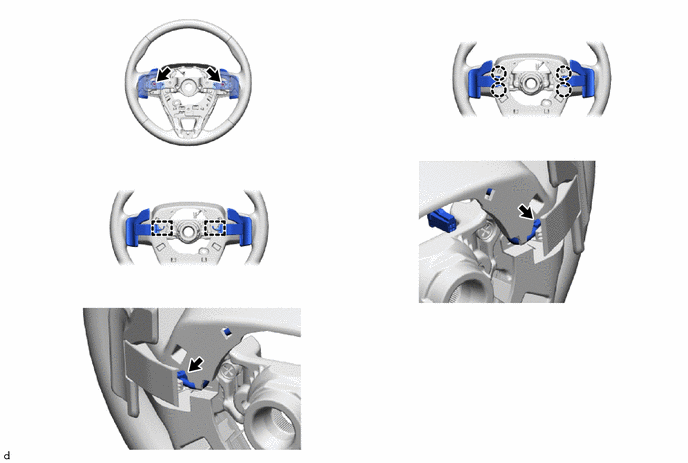
4. REMOVE NO. 1 SWITCH WIRE
HINT:
Perform this procedure only when replacement of the No. 1 switch wire is necessary.