Front suspension arm sub–assy lower no.1 Lh
: components:
1. Remove front wheel 2. Disconnect front stabilizer link assy lh (lh (a/t) position) 3. Disconnect front stabilizer link assy rh (lh (a/t) position) Hint: remove the rh side by the same procedures as the lh side.
4. Separate front suspension arm sub–assy lower no.1 Lh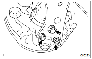
- Remove the bolt and 2 nuts, and separate the front suspension arm sub–assy lower no.1 Lh from the lower ball joint assy front lh.
: remove the rh side by the same procedures as the lh side.
6. Separate rack & pinion power steering gear assy (lh (a/t) position)- remove the 4 bolts, separate the rack & pinion power steering gear assy.
: loosen the bolt since the nut cannot be rotated.
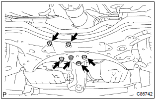
- Remove the 3 bolts and 3 nuts, disconnect the transverse engine engine mounting insulator and engine mounting member sub–assy center from the front suspension crossmember sub–assy.
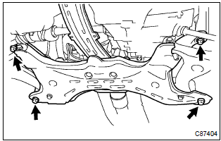
- Remove the 4 bolts.
- lower the transmission jack, remove the front suspension crossmember sub–assy.
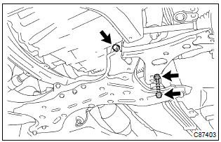
- Remove the 2 bolts, nut and front suspension arm sub– assy lower no.1 Lh from the front suspension crossmember sub–assy.
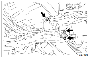
- Install the front suspension arm sub–assy lower no. 1 Lh, temporarily tighten the 2 bolts and nut.
- lift the front suspension crossmember sub–assy up with a transmission jack.
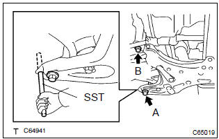
- Insert sst to the base hole of the rh side crossmember and rh side of the vehicle.
Sst 09670–00010
- tighten the bolt temporarily in the order a and b.
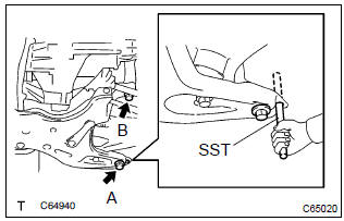
- Insert sst to the base hole of the lh side of crossmember and lh side of the vehicle.
Sst 09670–00010
- tighten the bolt temporarily in the order a and b.
- insert sst to the base hole of the rh side of crossmember and rh side of the vehicle.
Sst 09670–00010
- Then tighten the bolt a and b by the specified torque.
Torque:
bolt a: 157 nvm (1,601 Kgf·cm, 116 ft·lbf) bolt b: 113 nvm (1,152 Kgf·cm, 83 ft·lbf) - insert sst to the base hole of the lh side of crossmember and lh side of the vehicle.
Sst 09670–00010
- tighten the bolt a and b by the specified torque.
Torque:
bolt a: 157 nvm (1,601 Kgf·cm, 116 ft·lbf) bolt b: 113 nvm (1,152 Kgf·cm, 83 ft·lbf)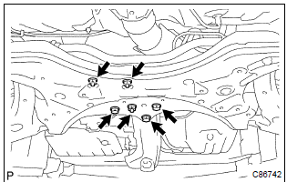
- Connect the transverse engine engine mounting insulator and engine mounting member sub–assy center to the front suspension crossmember sub–assy.
- install the 3 bolts and 3 nuts.
Torque: 52 nvm (530 Kgf·cm, 38 ft·lbf)
- install the rack & pinion power steering gear assy with the 4 bolts.
Torque: 58 nvm (591 Kgf·cm, 43 ft·lbf)
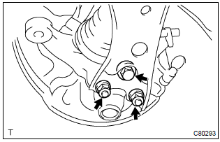
- Install the front suspension arm sub–assy lower no.1 Lh with the 2 nuts and bolt to the lower ball joint assy front lh.
Torque: 89 nvm (908 Kgf·cm, 66 ft·lbf)
: install the rh side by the same procedures as the lh side.
15. Install front stabilizer link assy lh (lh (a/t) position) 16. Install front stabilizer link assy rh (lh (a/t) position) Hint: install the rh side by the same procedure as the lh side.
17. Stabilize suspension- install the front wheel and jack down the vehicle.
Torque: 103 nvm (1,050 Kgf·cm, 76 ft·lbf)
- bounce the vehicle up and down several times to stabilize the suspension.
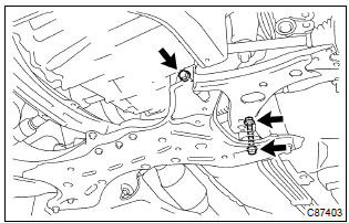
- Fully tighten the 2 bolts and nut.
Torque: 137 nvm (1,397 Kgf·cm, 101 ft·lbf)
: tighten the bolt since the nut cannot be rotated.
19. Inspect and adjust front wheel alignmentTest yourself
A quick Toyota Corolla quiz: every answer comes with an explanation and a link to the manual page.