Park assist / monitoring
No. 2 Clearance Warning Buzzer Circuit
In this manual: Park assist / monitoring
6steps
~36min
2/5difficulty
Done 0 of 6
DESCRIPTION
The clearance warning ECU receives the ultrasonic sensor signal to sound the rear warning buzzer.
WIRING DIAGRAM
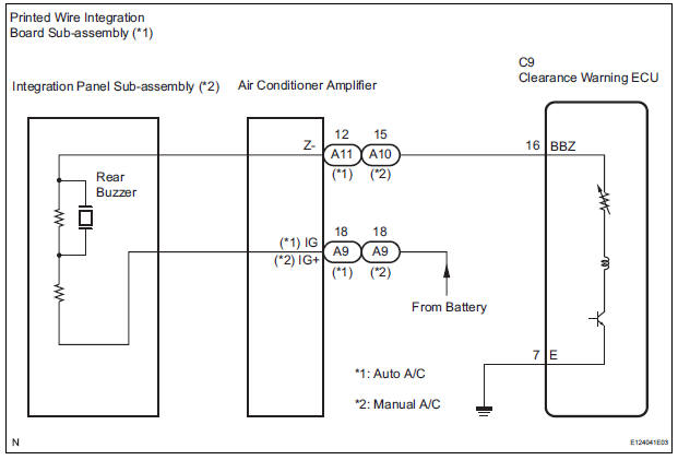
INSPECTION PROCEDURE
1 CHECK HARNESS AND CONNECTOR (CLEARANCE WARNING ECU - AIR CONDITIONER AMPLIFIER)
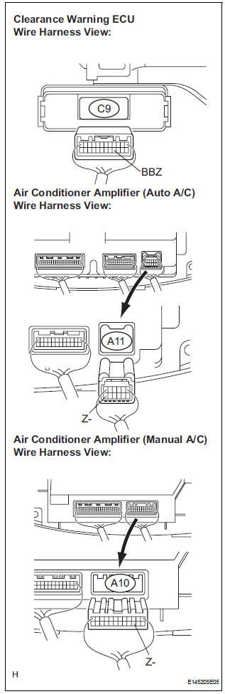
- Disconnect the connectors from the clearance warning ECU C9 and air conditioner amplifier connector A10 or A11.
- Measure the resistance according to the value(s) in the table below.
Standard resistance

2 INSPECT REAR BUZZER
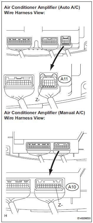
- Remove the integration control & panel assembly with the connectors still connected.
- Using a service wire, ground the terminal Z- of the integration control & panel assembly connector.
- Turn the ignition switch ON.
- Check that the rear buzzer sounds.
HINT: The clearance warning buzzer is separately excited, and will not sound unless an alternating voltage is applied.
OK: Operating noise (clicking sounds) can be heard.
Result
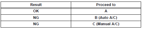
PROCEED TO NEXT CIRCUIT INSPECTION SHOWN IN PROBLEM SYMPTOMS TABLE
3 INSPECT PRINTED WIRE INTEGRATION BOARD SUB-ASSEMBLY
- Check that the malfunction disappears when a known good printed wire integration board sub-assembly is installed.
OK: Malfunction disappears.
REPLACE PRINTED WIRE INTEGRATION BOARD SUB-ASSEMBLY
4 INSPECT INTEGRATION PANEL SUB-ASSEMBLY
- Check that the malfunction disappears when a known good integration panel sub-assembly is installed.
OK: Malfunction disappears
REPLACE INTEGRATION PANEL SUB-ASSEMBLY
Test yourself
A quick Toyota Sienna quiz: every answer comes with an explanation and a link to the manual page.
Was this page helpful?