Vehicle Interior
Door Control Switch(for Front Rh)
Components
COMPONENTS
ILLUSTRATION 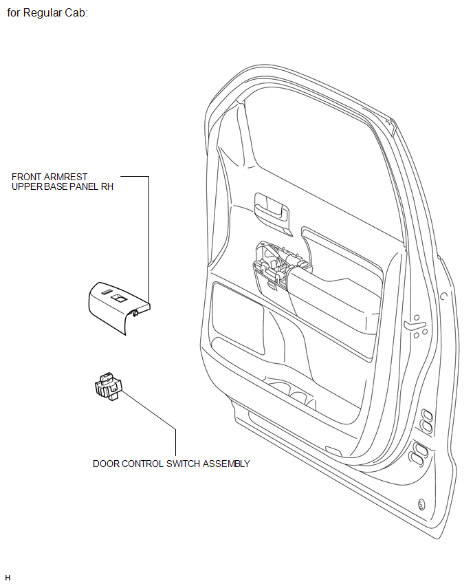
ILLUSTRATION 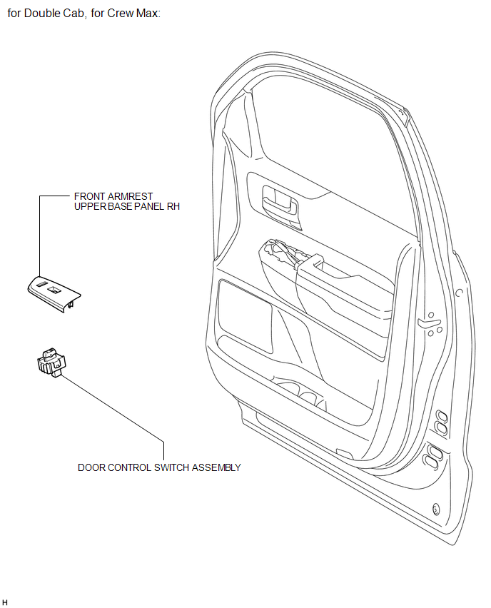
Inspection
INSPECTION
PROCEDURE
1. INSPECT DOOR CONTROL SWITCH ASSEMBLY 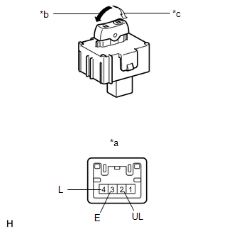
(a) Measure the resistance according to the value(s) in the table below.
Standard resistance:
Tester Connection | Switch Condition | Specified Condition |
4 (L) - 3 (E) |
Lock |
Below 1 Ω |
4 (L) - 3 (E) |
OFF |
10 kΩ or higher |
2 (UL) - 3 (E) |
2 (UL) - 3 (E) |
Unlock |
Below 1 Ω |
If the result is not as specified, replace the door control switch assembly. Text in Illustration
*a |
Component without harness connected
(Door Control Switch Assembly) |
*b |
Unlock |
*c |
Lock |
Installation
INSTALLATION
PROCEDURE
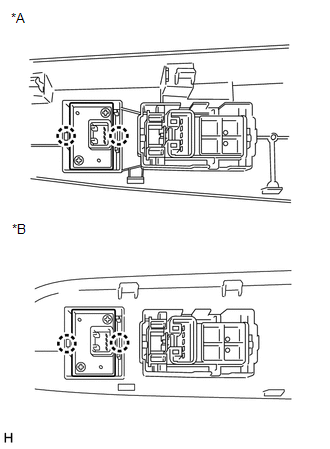
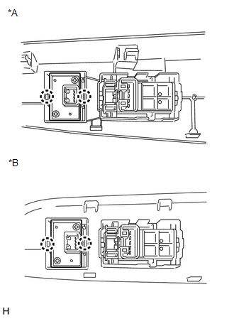
1. INSTALL DOOR CONTROL SWITCH ASSEMBLY
(a) Attach the 2 claws to install the door control switch assembly. Text in Illustration
*A |
for Regular Cab |
*B |
for Double Cab, for CrewMax |
|
 |
2. INSTALL FRONT ARMREST UPPER BASE PANEL RH
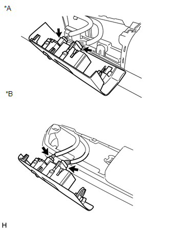
(a) Connect each connector. Text in Illustration
*A |
for Regular Cab |
*B |
for Double Cab, for CrewMax |
|
 |
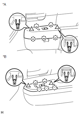
(b) Attach the 2 clips and 5 claws to install the front armrest upper base panel RH. Text in Illustration
*A |
for Regular Cab |
*B |
for Double Cab, for CrewMax |
|
 |
Removal
REMOVAL
PROCEDURE
1. REMOVE FRONT ARMREST UPPER BASE PANEL RH
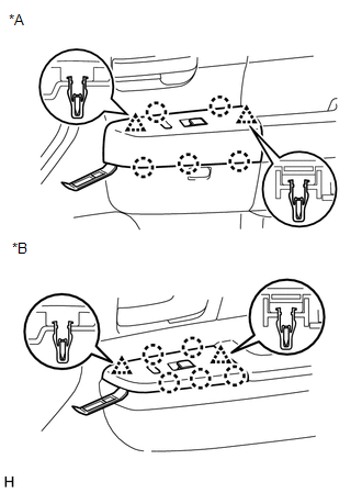
(a) Using a moulding remover, detach the 2 clips and 5 claws, and remove the front armrest upper base panel RH. Text in Illustration
*A |
for Regular Cab |
*B |
for Double Cab, for CrewMax |
|
 |
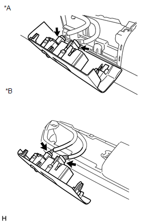
(b) Disconnect each connector. Text in Illustration
*A |
for Regular Cab |
*B |
for Double Cab, for CrewMax |
|
 |
2. REMOVE DOOR CONTROL SWITCH ASSEMBLY
(a) Detach the 2 claws and remove the door control switch assembly. Text in Illustration
*A |
for Regular Cab |
*B |
for Double Cab, for CrewMax |
|
 |
|
Was this page helpful?