Audio, Visual, Telematics

Indicator Circuit

~1min read

DESCRIPTION

The sonar ON/OFF indicator light and warning indicator lights are installed in the combination meter assembly.

WIRING DIAGRAM
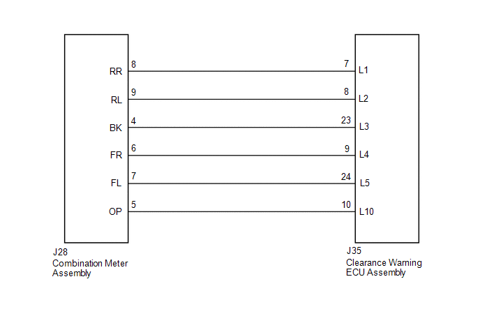
PROCEDURE

  1. CHECK HARNESS AND CONNECTOR (CLEARANCE WARNING ECU ASSEMBLY - COMBINATION METER ASSEMBLY)

(a) Disconnect the J35 clearance warning ECU assembly connector.

(b) Disconnect the J28 combination meter assembly connector.

(c) Measure the resistance according to the value(s) in the table below.

Standard Resistance:

Tester Connection

Condition

Specified Condition

J35-7 (L1) - J28-8 (RR)

Always

Below 1 Ω

J35-8 (L2) - J28-9 (RL)

Always

Below 1 Ω

J35-23 (L3) - J28-4 (BK)

Always

Below 1 Ω

J35-9 (L4) - J28-6 (FR)

Always

Below 1 Ω

J35-24 (L5) - J28-7 (FL)

Always

Below 1 Ω

J35-10 (L10) - J28-5 (OP)

Always

Below 1 Ω

J35-7 (L1) - Body ground

Always

10 kΩ or higher

J35-8 (L2) - Body ground

Always

10 kΩ or higher

J35-23 (L3) - Body ground

Always

10 kΩ or higher

J35-9 (L4) - Body ground

Always

10 kΩ or higher

J35-24 (L5) - Body ground

Always

10 kΩ or higher

J35-10 (L10) - Body ground

Always

10 kΩ or higher

NG

REPAIR OR REPLACE HARNESS OR CONNECTOR

OK
  1. CHECK COMBINATION METER ASSEMBLY

(a) Replace the combination meter assembly with a normally functioning or new one (See page ).

(b) Check that the multi-information display in the combination meter assembly operates normally.

OK:

Multi-information display in the combination meter assembly operates normally.

OK

END (COMBINATION METER ASSEMBLY IS DEFECTIVE)

NG

PROCEED TO NEXT SUSPECTED AREA SHOWN IN PROBLEM SYMPTOMS TABLE