Terminals Of Ecu
TERMINALS OF ECU1. CHECK NAVIGATION RECEIVER ASSEMBLY 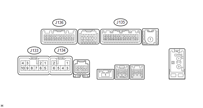
(a) Disconnect the J133 and J135 navigation receiver assembly connectors. (b) Measure the voltage and resistance according to the value(s) in the table below.
(c) Reconnect the J133 and J135 navigation receiver assembly connectors. (d) Measure the voltage and waveform according to the value(s) in the table below.
(e) Using an oscilloscope, check the waveform. 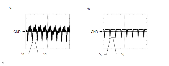
(1) Waveform 1 Measurement Condition
HINT: The video waveform changes according to the image sent by the television camera assembly. (2) Waveform 2 Measurement Condition
HINT: The video waveform changes according to the image sent by the television camera assembly. |