Seat Heater Switch
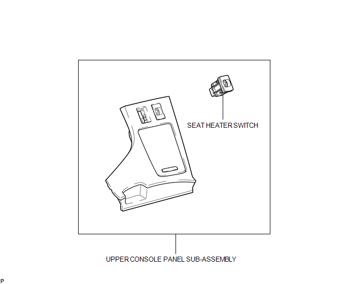
Removal REMOVAL PROCEDURE
1. REMOVE UPPER CONSOLE PANEL SUB-ASSEMBLY

2. REMOVE SEAT HEATER SWITCH
(a) Disengage the 2 claws and remove the seat heater switch as shown in the illustration. |
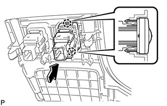 |
1. INSPECT SEAT HEATER SWITCH
(a) Inspect the driver side seat heater switch operation. (1) Measure the resistance according to the value(s) in the table below. Standard Resistance:
If the result is not as specified, replace the switch. (2) Turn the seat heater switch on and check if the seat heater switch indicator comes on. OK:
If the result is not as specified, replace the switch. |
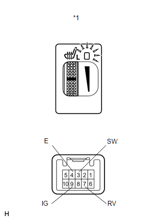 |
(b) Inspect the front passenger side seat heater switch operation. (1) Measure the resistance according to the value(s) in the table below. Standard Resistance:
If the result is not as specified, replace the switch. (2) Turn the seat heater switch on and check if the seat heater switch indicator comes on. OK:
If the result is not as specified, replace the switch. |
 |
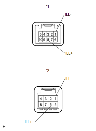
(c) Check if the seat heater switch indicator comes on. OK: Driver Side
If the result is not as specified, replace the switch. |
 |
1. INSTALL SEAT HEATER SWITCH
(a) Engage the 2 claws and install the seat heater switch as shown in the illustration. |
 |
2. INSTALL UPPER CONSOLE PANEL SUB-ASSEMBLY

Test yourself
A quick Toyota Venza quiz: every answer comes with an explanation and a link to the manual page.