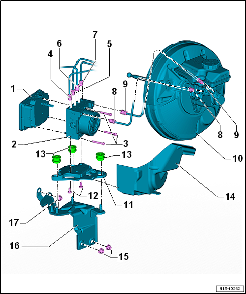
Assembly overview - control unit and hydraulic unit, LHD vehicles
In this manual: Brake system
~2min read
Tightening torque found on this page
1 -
ABS control unit -J104-
Removing and installing → Chapter.
2 -
ABS hydraulic unit -N55-
Removing and installing → Chapter.
3 -
Torx bolt
Tighten new Torx bolts alternately in 2 stages
1. stage: temporary tightening torque: 1 N·m to 1,5 N·m.
2. stage: final specified torque: 2,5 N·m.
4 -
Brake line
To rear right brake caliper.
Identification: 5.25 mm in diameter and union nut with thread M 12 x 1
14 N·m
5 -
Brake line
To front left brake caliper.
Identification: 5.25 mm in diameter and union nut with thread M 10 x 1
14 N·m
6 -
Brake line
To front right brake caliper
Identification: 5.25 mm in diameter and union nut with thread M 12 x 1
14 N·m
7 -
Brake line
To rear left brake caliper.
Identification: 5.25 mm in diameter and union nut with thread M 10 x 1
14 N·m
8 -
Brake line
From primary piston circuit of brake master cylinder to hydraulic unit.
Identification: 6 mm in diameter, union nut with thread M 12 x 1
14 N·m
9 -
Brake line
From secondary piston circuit of brake master cylinder to hydraulic unit.
Identification: 6 mm in diameter and union nut with thread M 12 x 1
14 N·m
10 -
Brake servo
Removing and installing → Chapter.
11 -
Bracket
12 -
Torx bolt
8 N·m
13 -
Rubber damper
Ensure that rubber dampers of retainer are not pressed out of bracket when installing. After installation, check that the ABS hydraulic unit -N55- is firmly seated, or malfunction can occur.
14 -
Heat shield
Allocation → Electronic Parts Catalogue (ETKA).
15 -
Hexagon nut
20 N·m
16 -
Bracket
17 -
Hexagon nut
20 N·m
?
Test yourself
A quick Volkswagen Golf quiz: every answer comes with an explanation and a link to the manual page.