Body exterior
Lock Carrier
In this manual: Body exterior
19steps
~114min
4/5difficulty
Done 0 of 19
Tools
Required Special Tools and Equipment
Special tools and workshop equipment required
- Guide Pins -T10093
- Torque Wrench 1331 5-50Nm -VAG1331-
- Torque Wrench 1332 40-200Nm -VAG1332
Overview - Lock Carrier
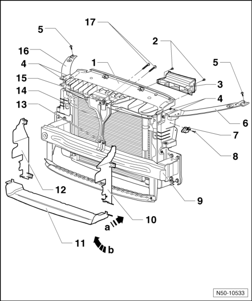
- Lock Carrier with Attachments
- Removing and installing
- Service position
- Screw
- Tightening specification: 2 N·m
- Quantity: 2
- Air Duct
- Bolt
- Tightening specification: 8 N·m
- 2 per page
- Bolt
- Tightening specification: 8 N·m
- 1 per side
- Left Bracket
- Driver Front Airbag Crash Sensor
- Not for all countries
- Left and right
- For driver front airbag crash sensor
- For passenger front airbag crash sensor
- Bolt
- Tightening specification: 6 N·m
- Crossmember
- Left Air Vent
- Lower Air Vent
- Right Air Vent
- Bolt
- Tightening specification: 8 N·m
- Quantity: 2
- Lock Support
- Lock
- Left Bracket
- Bolt
- Tightening specification: 12 N·m.
- Quantity: 2
Service Position
Moving into Service Position
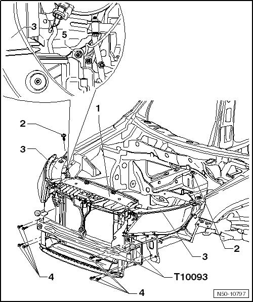
- Remove the front bumper cover (18º slope angle).
- Remove the front bumper cover (28º slope angle).
- In vehicles with charge air cooler, loosen the pressure hoses.
- Remove the bolts -4- at left and right longitudinal member.
- Remove rear bolt -5- from the left and right headlamp.
- Install the Guide Pins - T 10093- on the left and right longitudinal member.
- Remover the left and right bolts -2- at the top of the brackets -3-.
- The lock carrier -1- with the brackets -3- can be pulled approximately 10 cm forward onto the Guide Pins -T10093-.
Service Position, Resetting
Install in reverse order of removal.
- For bolt tightening specifications, see the overview.
- Align the lock carrier with the attachments on the longitudinal members and between the fenders.
- Secure the headlamp and check the headlamp setting.
Note
- Make sure that pressure hoses for charge air cooler are re-engaged correctly.
- Hoses and lines must not be pinched.
Pressure Hoses, Removing
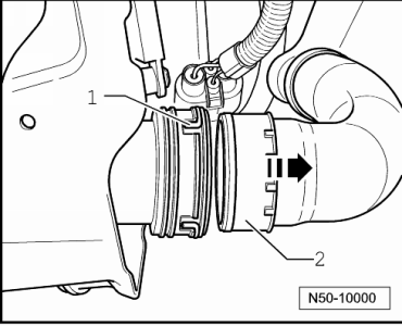
- Disengage connector coupling -1- and disconnect pressure hose -2- in direction of -arrow- from coupling.
- When connecting the pressure hoses, make sure that the connector coupling engages audibly.
Lock Carrier with Attachments, Removing and Installing
Removing
Note
- The lock carrier is a safety-related component and for this reason it may not be serviced.
- If damaged, replace the lock carrier.

- Bring the lock carrier and its attachments into the service position -1-.
- Disconnect the any connectors present.
- Disconnect the connector for the crash sensor.
- Drain the coolant and disconnect the coolant line.
- Disconnect the condenser lines.
- With a second technician, remove the Guide Pins -T10093- from the longitudinal member on left and right sides and lift out the lock carrier.
WARNING
Do not start the engine whenever the A/C system or coolant lines are disconnected.
Note
- Do not hang the condenser and hydraulic oil cooler by the lines.
- Do not kink the condenser and hydraulic lines.
Installing
Install in reverse order of removal.
- Make sure that all plug- and hose connections are correctly installed when re-assemble.
- The brackets on the longitudinal member must be installed.
- For bolt tightening specifications, see the overview.
- Align the lock carrier with the longitudinal members and between the fenders.
- Secure the headlamp and check the headlamp setting.
Overview - Bracket for Bumper Bracket

- Bracket
- Left and right
- Bolt
- Quantity: 2 on each side
- Tightening specification: 55 N·m
Test yourself
A quick Volkswagen Tiguan quiz: every answer comes with an explanation and a link to the manual page.
Was this page helpful?