Power Driver Seat
Tools
Special tools and workshop equipment required
- Engine and Gearbox Bracket VAS6095A -VAS6095A-

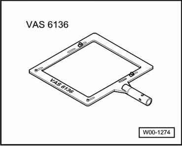
- Engine/Transmission Holder - Seat Repair Fixture -VAS6136-
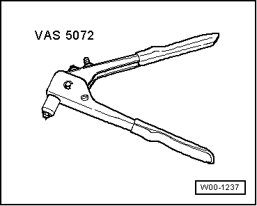
- Pop Rivet Nut Pliers -VAS5072A-
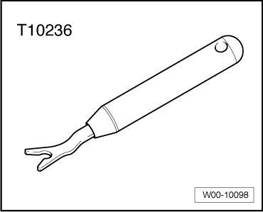
- Window Release Tool -T10236-
Sill-Side Trim Panel, Removing and Installing
Removing
- Switch off the ignition.
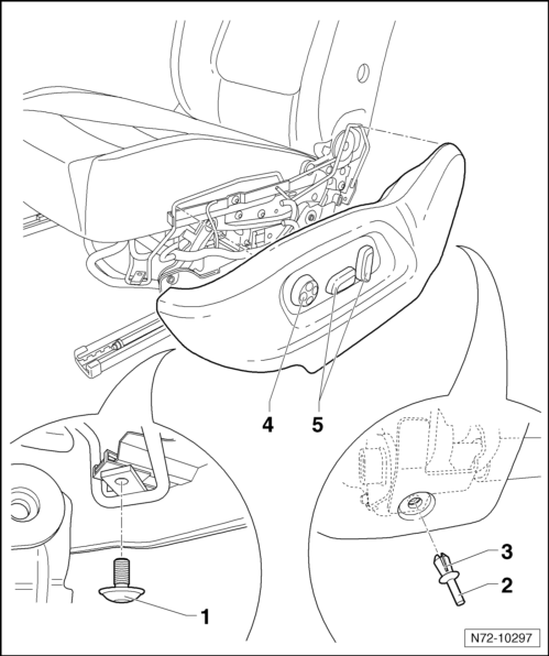
- Remove the bolt -1- (2 N·m).
- Press the clamping pin -2- inward and remove the expanding clip -3-.
- Pull the trim panel outward off the seat.
- Disconnect the wiring harness from the Driver Seat Lumbar Support Adjustment Switch -E176--4- and from the Driver Seat Adjustment Control Head -E470--5-.
- Remove the wiring harness from the trim panel.
Installing
- Install in reverse order of removal.
Switch, Removing and Installing
The following switches are installed in the sill-side trim panel:
- Driver Seat Lumbar Support Adjustment Switch -E176-
- Driver Seat Adjustment Control Head -E470-
Removing
- Switch off the ignition.
- Remove the sill-side trim panel.
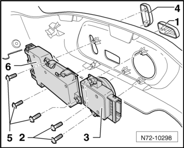
- Carefully remove the button -1- from the lumbar support switch -3- using the Window Release Tool -T10236-.
- Remove the two screws -2- (1 N·m) and remove the lumbar adjustment switch -3- from the trim panel.
- Carefully remove the button -4- from the seat adjustment control head -6- using the Window Release Tool -T10236-.
- Remove the three screws -5- (1 N·m) and remove the seat adjustment control head -6- from the trim panel.
Installing
- Install in reverse order of removal.
Sill-Side Trim Panel Bracket, Removing and Installing
Removing
- Remove the sill-side trim panel.
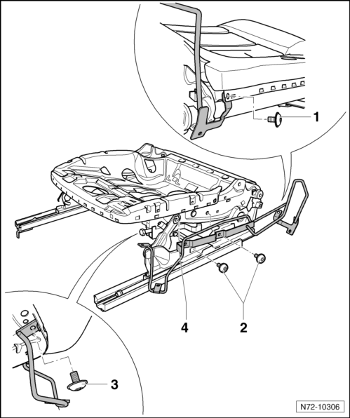
- Remove the cover in the area of the screw -1- and lift the cushion slightly.
- Remove the bolt -1- (8 N·m).
- Remove the bolt -2- (8 N·m).
- Remove the two bolts -3- (8 N·m).
- Loosen the bracket -4- from the seat frame.
Installing
- Install in reverse order of removal.
Seat Forward/Backward Adjuster, Removing and Installing
Note
The motor for the seat forward/backward adjustment cannot be replaced separately. It can only be replaced with the seat pan lower frame.
Removing
- Remove the headrests.
- Position the seat as high as possible.
- Mount the Engine/Transmission Holder - Seat Repair Fixture -VAS6136- on the Engine and Gearbox Bracket -VAS6095A-.
- Remove the front seat.
- Secure the seat to the Engine/Transmission Holder - Seat Repair Fixture -VAS6136-.
- Remove the front seat belt latch.
- Remove the tunnel-side trim panel.
- Remove the sill-side trim panel.
- Remove the wiring harnesses from the seat lower frame.
- Remove the bracket, trim panel, and sill-side.
- Disconnect the wiring harness form the seat forward/backward adjustment motor.
- Remove the screw -1- on the seat frame on the door sill side from the height adjustment drive.
- Secure the spindle mount -2- from rotating.
- Remove the front screws -5- and -6-.
- Remove the rear screws -3- and -4-.

- Pull the seat pan -1- upward from the seat pan lower frame -2-.

Installing
- Place the seat pan -1- on the seat pan lower frame -2-.

Note
- The bolts are microencapsulated and must therefore be replaced after every removal.
- Before installing the new bolts, the threads of the corresponding nuts must be cleaned.
Caution
Mount all the screws by hand to prevent damaging the threaded bushings and the bearing bushings.
- Tighten the rear bolts -3- and -4- to 22 N·m.
- Remove the anti-twist mechanism for the spindle mount -2-.
- Tighten the bolt -1- for the height adjustment drive to 18 N·m.
- Tighten the front bolts -5- and -6- to 22 N·m.
- Connect the seat forward/backward adjustment motor wiring harness.

- Installation is performed in reverse order of the removal.
Backrest Adjustment Drive, Removing and Installing
Removing
- Mount the Engine/Transmission Holder - Seat Repair Fixture -VAS6136- on the Engine and Gearbox Bracket -VAS6095A-.
- Remove the front seat.
- Secure the seat to the Engine/Transmission Holder - Seat Repair Fixture -VAS6136-.
- Press the release button if equipped and pull the headrest out of the backrest.
- Remove the headrest.
- Remove the front seat belt latch.
- Remove the tunnel-side trim panel.
- Remove the sill-side trim panel.
- Disconnect the two backrest motor wiring harnesses on the bottom side of the seat frame. Detach the wiring harnesses from the seat frame.
- Remove the backrest.
- Remove the backrest and folding table, if equipped.
- Remove the cover and cushion from the front seat backrest.
- Disconnect the wiring harness from the backrest adjustment motor.
- Remove the bolt -1- (7.5+1 N·m).
- Remove the nut -2- (8 +- 1 N·m).
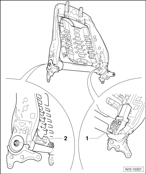
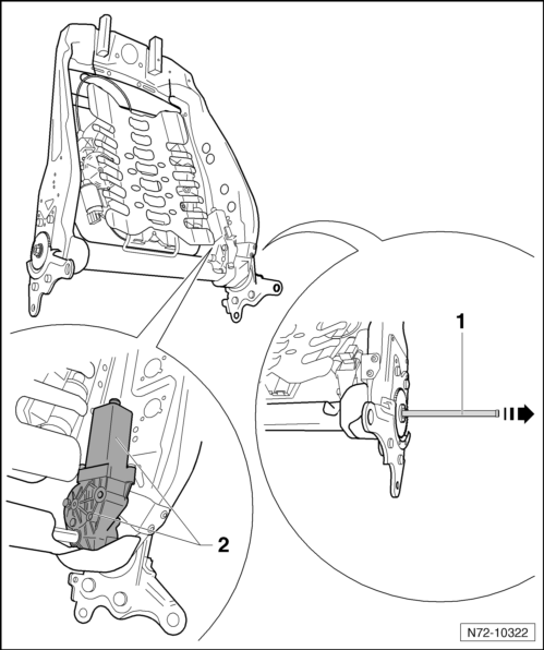
- Remove the transfer rod -1- from the backrest frame -arrow-.
- Remove the drive for the backrest adjustment -2- from the backrest frame.
Installing
- Install in reverse order of removal.
After successful installation perform a basic setting in "ODIS SERVICE".
Select "Guided Fault Finding" in ODIS Service.
- After all control modules were checked:
- Select "Separate test plan".
- Select "Function/component selection".
- Select "Body".
- Body Repairs"
- Select "01 - OBD-capable systems".
- Select "Driver side seat adjustment".
- Select "Functions".
- Select "Calibration".
Angle Adjustment Drive, Removing and Installing
Removing
- Remove the headrests.
- Position the seat as high as possible.
- Mount the Engine/Transmission Holder - Seat Repair Fixture -VAS6136- on the Engine and Gearbox Bracket -VAS6095A-.
- Remove the front seat.
- Secure the seat to the Engine/Transmission Holder - Seat Repair Fixture -VAS6136-.
- Remove the front seat belt latch.
- Remove the tunnel-side trim panel.
- Remove the sill-side trim panel.
- Remove the wiring harnesses from the seat lower frame.
- Disconnect the wiring harness from the seat forward/backward adjustment motor.
- Disconnect the wiring harness from the angle adjustment motor.
- Remove the front screws -5- and -6-.
- Loosen the seat in the front from the lower frame and swivel it toward the rear.

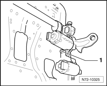
- Remove the bolt -1-.
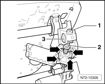
- Remove the four screws -arrows- and remove the motor.
- Secure the spindle -2- from rotating with pliers and remove the screw -1-.
- Remove the spindle -2- from the spindle nut -3-.
Installing
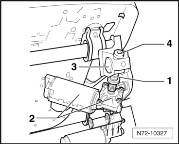
- Rotate the spindle -1- from the drive -2- as far as possible into the spindle nut -3-.
- Install the screw -4- by hand into the spindle so that it is loose.
Note
It is only possible to tighten the bolt -4- to the tightening specification when the seat is inside the vehicle and connected to the vehicle electrical system.
- Secure the drive with the bolt -1- (6+2 N·m).
Installation is performed in reverse order of the removal.
- Seat installed in the vehicle and connected to the vehicle electrical system
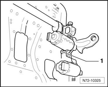
- Move the seat down using the angle adjustment and at the same time, tighten the bolt -4- to 8 +- 1 N·m.
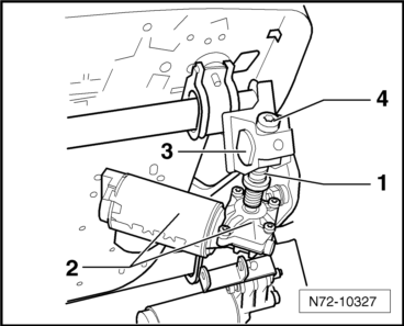
Height Adjustment Drive, Removing and Installing
Removing
- Remove the headrests.
- If possible, move the seat into the highest seating position.
- Mount the Engine/Transmission Holder - Seat Repair Fixture -VAS6136- on the Engine and Gearbox Bracket -VAS6095A-.
- Remove the front seat.
- Secure the seat to the Engine/Transmission Holder - Seat Repair Fixture -VAS6136-.
- Remove the front seat belt latch.
- Remove the tunnel-side trim panel.
- Remove the sill-side trim panel.
- Remove the bracket, trim panel, and sill-side.
- Remove the wiring harnesses from the seat lower frame.
- Disconnect the wiring harness form the seat height adjustment motor.
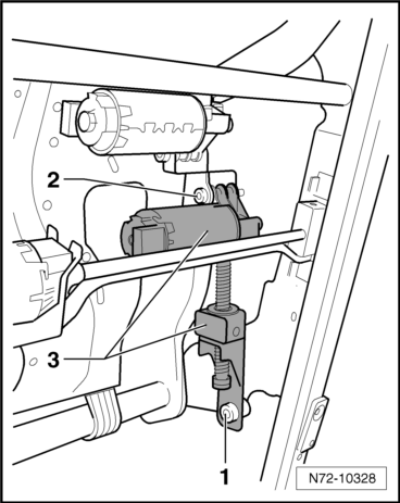
- Remove the bolt -1- (18 +- 2 N·m).
- Remove the bolt -2- (6 + 2 N·m).
- Remove the drive -3- from the seat frame.
Installing
- Install in reverse order of removal.
Four-Way Electric Lumbar Support, Removing and Installing
Removing
- Mount the Engine/Transmission Holder - Seat Repair Fixture -VAS6136- on the Engine and Gearbox Bracket -VAS6095A-.
- Remove the front seat.
- Secure the seat to the Engine/Transmission Holder - Seat Repair Fixture -VAS6136-.
- Press the release button if equipped and pull the headrest out of the backrest.
- Remove the headrest.
- Remove the front seat belt latch.
- Remove the tunnel-side trim panel.
- Remove the sill-side trim panel.
- Disconnect the two backrest motor wiring harnesses on the bottom side of the seat frame. Detach the wiring harnesses from the seat frame.
- Remove the backrest.
- Remove the backrest and folding table, if equipped.
- Remove the cover and cushion from the front seat backrest.
- Remove the wiring harnesses from the lumbar adjustment motors.
- Drill out the rivet -1- on the back side of the backrest.
- Remove the lumbar support -2- from the backrest frame.
- Remove the lumbar support -2- from both brackets -3- and -4- in the upper front area of the backrest frame.

Installing
- Install in reverse order of removal.
Use Pop Rivet Nut Pliers -VAS5072A- to install the rivet.
Test yourself
A quick Volkswagen Tiguan quiz: every answer comes with an explanation and a link to the manual page.