Interruptor de control de puerta (lado del conductor)
Desmontaje
DESMONTAJE
COMPONENTES (DESMONTAJE)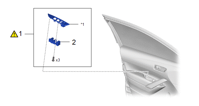
Procedimiento | Código del nombre de la pieza |  |  |  |
|
|---|---|---|---|---|---|
1 |
CONJUNTO DEL INTERRUPTOR MAESTRO DE LA RED MULTIPLEX CON PANEL SUPERIOR DE LA BASE DEL APOYABRAZOS DELANTERO IZQUIERDO |
- |
 |
- |
- |
2 |
CONJUNTO DEL INTERRUPTOR MAESTRO DE RED MULTIPLEX |
84040 |
- |
- |
- |
*1 |
PANEL SUPERIOR DE LA BASE DEL APOYABRAZOS DELANTERO IZQUIERDO |
- |
- |
PROCEDIMIENTO
1. RETIRE EL CONJUNTO DEL INTERRUPTOR MAESTRO DE LA RED MULTIPLEX CON PANEL SUPERIOR DE LA BASE DEL APOYABRAZOS DELANTERO IZQUIERDO
|
Haga clic aquí |
2. DESMONTE EL CONJUNTO DEL INTERRUPTOR PRINCIPAL DE LA RED MULTIPLEXADA

Inspección
INSPECCIÓN
PROCEDIMIENTO
1. INSPECCIONE EL CONJUNTO DEL INTERRUPTOR PRINCIPAL DE LA RED MULTIPLEXADA
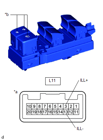
(a) Compruebe que el LED se ilumine. (1) Aplique voltaje de la batería auxiliar al conjunto del interruptor maestro de la red multiplexada y compruebe que el LED se ilumina. OK:
Si el resultado no es el especificado, sustituya el conjunto del interruptor principal de la red multiplexada. |
|
Instalación
INSTALACIÓN
COMPONENTES (MONTAJE)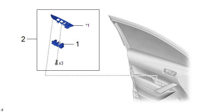
Procedimiento | Código del nombre de la pieza |  |  |  |
|
|---|---|---|---|---|---|
1 |
CONJUNTO DEL INTERRUPTOR MAESTRO DE RED MULTIPLEX |
84040 |
- |
- |
- |
2 |
CONJUNTO DEL INTERRUPTOR MAESTRO DE LA RED MULTIPLEX CON PANEL SUPERIOR DE LA BASE DEL APOYABRAZOS DELANTERO IZQUIERDO |
- |
- |
- |
- |
*1 |
PANEL SUPERIOR DE LA BASE DEL APOYABRAZOS DELANTERO IZQUIERDO |
- |
- |
PROCEDIMIENTO
1. INSTALE EL CONJUNTO DEL INTERRUPTOR PRINCIPAL DE LA RED MULTIPLEXADA
2. INSTALE EL CONJUNTO DEL INTERRUPTOR MAESTRO DE LA RED MULTIPLEX CON PANEL SUPERIOR DE LA BASE DEL APOYABRAZOS DELANTERO IZQUIERDO