General information
Fuel evaporative emission control simply consists of internal venting of the carburettor float chamber and closed circuit fuel tank ventilation. Central Fuel Injection (CFI) engine models
To minimise the escape of unburned hydrocarbons, the fuel tank filler cap is sealed, and a charcoal canister collects the petrol vapours generated in the fuel tank when the car is parked. The canister stores them until they can be cleared from the canister (under the control of the fuel injection/ignition system electronic control unit) via the canister purge solenoid valve. When the valve is opened, the fuel vapours pass into the inlet tract, to be burned by the engine during normal combustion. Crankcase emission control OHV engines
On OHV engines a closed circuit crankcase ventilation system is used ensuring that blowby gases which pass the piston rings and collect in the crankcase, as well as oil vapour, are drawn into the combustion chambers to be burnt. The system consists of a vented engine oil filler cap connected by one hose to the inlet manifold and by another to the air cleaner. The gas flow is controlled by a calibrated port in the oil filler cap and by manifold vacuum according to throttle position.
CVH engines
On CVH engines a closed circuit crankcase ventilation system is also used (see illustration).
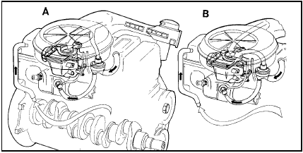
1.9 Typical crankcase ventilation system as used on CVH engines with carburettor
A Ventilation at idle with part-closed throttle B Ventilation at full throttle position
At light throttle openings, the emissions are drawn out of the rocker cover, through a control orifice in the crankcase ventilation filter (where fitted), and into the inlet manifold. Under full throttle conditions the gas flow routing is still as just described, but in addition the gases are drawn through a filter and pass into the air cleaner. This arrangement offsets any tendency for the fuel/air ratio to be adversely affected at full throttle. Exhaust emission control Carburettor engine models On carburettor engine models an exhaust emission control system is used of which the exact components fitted can vary according to model. In general the system operates as follows. To improve driveability during warm-up conditions and to keep exhaust emission levels to a minimum, a vacuum-operated, temperature-sensitive emission control system is fitted to OHV and CVH engines covered by this manual. The system is designed to ensure that the rate of distributor vacuum advance is compatible with the change in fuel/air mixture flow under all throttle conditions, thus resulting in more complete combustion and reduced exhaust emissions. Under part throttle cruising conditions, distributor vacuum advance is required to allow time for the fuel/air mixture in the cylinders to burn. When returning to a part throttle opening after accelerating or decelerating, the distributor vacuum increases before the fuel/air mixture has stabilised. On certain engines this can lead to short periods of incomplete combustion and increased exhaust emission. To reduce this condition a spark delay valve is incorporated in the vacuum line between the carburettor and distributor to reduce the rate at which the distributor advances. Under certain conditions, particularly during the period of engine warm-up, some models may suffer from a lack of throttle response. To overcome this problem a spark sustain valve may be fitted in the vacuum line either individually or in conjunction with the spark delay valve. This valve is used to maintain distributor vacuum under transient throttle conditions, thus stabilising the combustion process.The operation of the valves is controlled by a ported vacuum switch (PVS) which has the vacuum lines connected to it. The PVS is actuated by the engine cooling water and is sensitive to changes in engine operating temperature. A fuel trap prevents fuel or fuel vapour from being drawn into the distributor vacuum unit (see illustrations).
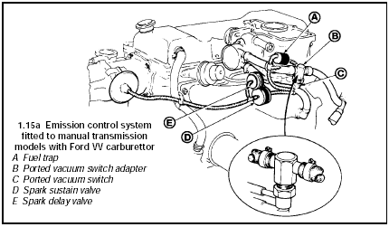
1.15a Emission control system fitted to manual transmission models with Ford VV carburettor
A Fuel trap
B Ported vacuum switch adapter C Ported vacuum switch
D Spark sustain valve
E Spark delay valve
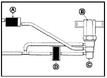
1.15b Alternative emission control system layout for manual transmission models with Ford VV carburettor
A Fuel trap
B Ported vacuum switch adapter C Ported vacuum switch
D Spark sustain valve
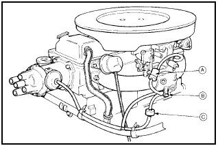
1.15c Emission control system layout for manual transmission models with Weber 2V carburettor
A Fuel trap
B Ported vacuum switch
C Spark sustain valve
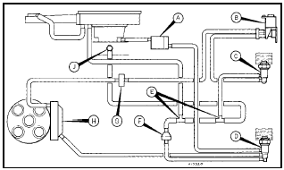
1.15d Emission control system layout for automatic transmission models with Ford VV carburettor
A Fuel trap
B Two-way solenoid
C Ported vacuum switch (blue) D Ported vacuum switch (green) E T-connectors
F Check valve
G Restrictor
H Dual diaphragm distributor J Inlet manifold connection
The carburettor speed control system is an integral part of the emission control system on some UK models as well as for some overseas market models (see illustration).

1.16 Carburettor speed control system layout
A Temperature vacuum switch B Carburettor speed control valve C Spark delay valve
D Ported vacuum switch and adapter
To minimise the amount of pollutants which escape into the atmosphere, a catalytic converter is fitted in the exhaust system of CFI engine models.
The system is of a closed loop type. A Heated Exhaust Gas Oxygen (HEGO) sensor located in the exhaust system provides the fuel injection/ignition electronic control unit with constant feedback, enabling the control unit to adjust the mixture to provide the best possible conditions for the converter to operate.
Test yourself
A quick Ford Escort quiz: every answer comes with an explanation and a link to the manual page.