Suspension
Trailing Arm Bushing - Removal and Installation
In this manual: Suspension
11steps
~81min
5/5difficulty
3special tools
Done 0 of 11
Special Service Tools / General Equipment
 |
205-199 (T83T-3132-A1) Spindle/Axle Installer T83-4000-A TKIT-1983-F TKIT-1983-FLM TKIT-1983-FX |
 |
205-353 (T95T-3132-C) Installer, Front Wheel Spindle Seal TKIT-1995-F TKIT-1995-FM/FLM |
 |
308-062 (T77J-7025-M) Installer, Input Shaft Bearing |
| Transmission Jack | |
| Vehicle/Axle Stands | |
Removal
NOTICE: Suspension fasteners are critical parts that affect the performance of vital components and systems. Failure of these fasteners may result in major service expense. Use the same or equivalent parts if replacement is necessary. Do not use a replacement part of lesser quality or substitute design. Tighten fasteners as specified.
- Remove the wheel and tire.
Refer to: Wheels and Tires (204-04A Wheels and Tires, Removal and Installation). - Support the rear axle assembly.
Use the general equipment: transmission jack.
- Remove the parking brake cable bracket nuts.
- Remove the axle bracket-to-frame bolts and remove the axle assembly.

- Both sides.
Lower the rear axle assembly, remove and discard the trailing arm nut and bolt.
- Using the special tools, remove the lower control arm bushing.
Use the special service tools: 205-199 (T83T-3132-A1) Installer, spindle/axle. , 205-353 (T95T-3132-C) Installer, front wheel spindle seal.
Installation
- Using the special tool, install the lower control arm bushing.
Use the special service tool: 308-062 (T77J-7025-M) Installer, input shaft bearing.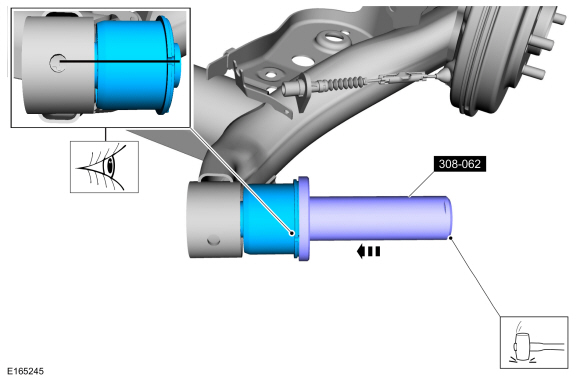
- Both sides.
Install the rear axle assembly and install the new lower control arm nut and bolt.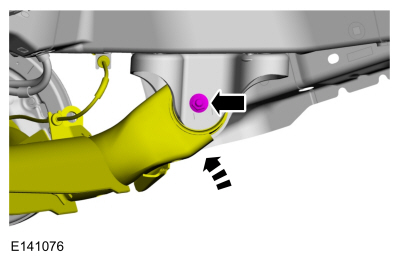
Install the rear axle assembly.- Install the parking brake cable bracket nuts.
Torque: 18 lb-ft (25 N·m)
- Install the axle bracket-to-frame bolts.
Torque: 92 lb-ft (125 N·m)
- Install the parking brake cable bracket nuts.
- Both sides.
Position an axle support jack under the beam axle. Raise the jack, maintaining a 5 mm clearance between the vehicle and the jack.
Use the general equipment: vehicle/axle stands.
- Both sides.
Tighten the new lower control arm nut and bolt.
Torque:
Stage 1: 59 lb-ft (80 N·m)
Stage 2: 120 degrees
- Install the wheel and tire.
Refer to: Wheels and Tires (204-04A Wheels and Tires, Removal and Installation).
Test yourself
A quick Ford Fiesta quiz: every answer comes with an explanation and a link to the manual page.
Was this page helpful?