Chassis
Brake Pedal and Bracket
In this manual: Chassis
6steps
~36min
2/5difficulty
Done 0 of 6
NOTE: 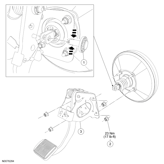
Removal and Installation All vehicles NOTICE: Do not service the brake pedal or brake booster without first removing the stoplamp switch and speed control deactivator switch. These switches must be removed with the brake pedal in the at-rest position. Switch plungers must be compressed for the switch to rotate in the bracket. Attempting to remove the switch when the plunger is extended (during pedal apply) will result in damage to the switch.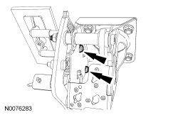
 All vehicles
Automatic transmission shown, manual transmission similar.
| Item | Part Number | Description |
|---|---|---|
| 1 | 2L523 | Brake booster actuating rod pin |
| 2 | W520212 | Brake booster retaining nut (4 required) |
| 3 | 2450 | Brake pedal and bracket assembly |
Removal and Installation All vehicles NOTICE: Do not service the brake pedal or brake booster without first removing the stoplamp switch and speed control deactivator switch. These switches must be removed with the brake pedal in the at-rest position. Switch plungers must be compressed for the switch to rotate in the bracket. Attempting to remove the switch when the plunger is extended (during pedal apply) will result in damage to the switch.
- Remove the stoplamp switch. For additional information, refer to Section 417-01.
- If equipped, remove the Clutch Pedal Position (CPP) switch. For additional information, refer to Section 303-14.
- Remove the 2 bolts and position the clutch master cylinder aside.
- To install, tighten bolts to 9 N·m.
- Remove the clutch master cylinder actuating rod from the clutch pedal.
All vehicles
- Remove the 4 brake booster nuts.
- To install, tighten to 23 N·m.
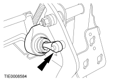
- Remove the brake booster actuating rod from the brake pedal in the following sequence.
- Disengage the tabs.
- Remove and discard the brake booster actuating rod pin.
- Remove the brake pedal bracket.
- NOTICE: Do not press, pull or otherwise move the brake pedal while installing the stoplamp switch or the speed control deactivator switch. These switches must be installed with the booster push rod attached to the brake pedal and with the brake pedal in the at-rest position. Installing these switches with the brake pedal in any other position will result in incorrect adjustment and may damage the switches.
To install, reverse the removal procedure.
- Install a new brake booster actuating rod pin.
Test yourself
A quick Ford Focus quiz: every answer comes with an explanation and a link to the manual page.
Was this page helpful?