Clutch Clearance Inspection (A/T)
- Clutch Compressor Attachment 07ZAE-PRP0100
Inspect the clutch piston, the discs, the plates, and the end-plate for wear and damage, and inspect the clutch wave-plate phase difference, if necessary.
Install the clutch piston in the clutch drum. Do not install the O-rings on the clutch piston during inspection.
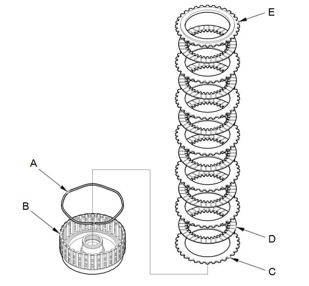
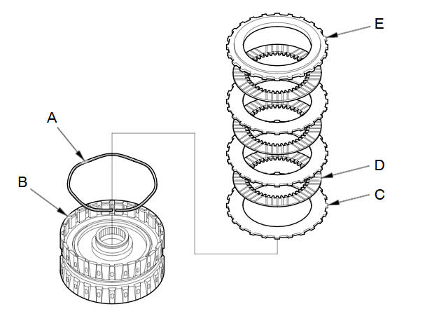
Install the wave spring (A) in the 1st clutch drum (B). Starting with the clutch wave-plate, alternately install the wave-plates (C) (6) and discs (D) (6). Install the clutch end-plate (E) with the flat side down on the top disc.
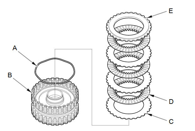
Install the wave spring (A) in the 2nd clutch drum (B). Starting with the clutch flat-plate, alternately install the flat-plates (C) (3) and the discs (D) (3). Install the clutch end-plate (E) with the flat side down on the top disc.
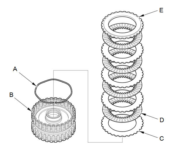
Install the wave spring (A) in the 4th clutch drum (B). Starting with the clutch flat-plate, alternately install the flat-plates (C) (4) and the discs (D) (4). Install the clutch end-plate (E) with the flat side down on the top disc.
Install the wave spring (A) in the 3rd clutch drum (B). Starting with the clutch wave-plate, alternately install the wave-plates (C) (3) and the discs (D) (3). Install the clutch end-plate (E) with the flat side down on the top disc.
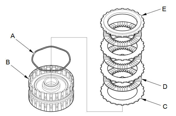
Install the wave spring (A) in the 5th clutch drum (B). Starting with the clutch wave-plate, alternately install the wave-plates (C) (3) and the discs (D) (3). Install the clutch end-plate (E) with the flat side down on the top disc.
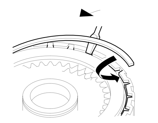
Install the snap ring with a screwdriver to secure the clutch end-plate.
Set a dial indicator (A) on the clutch end-plate (B).
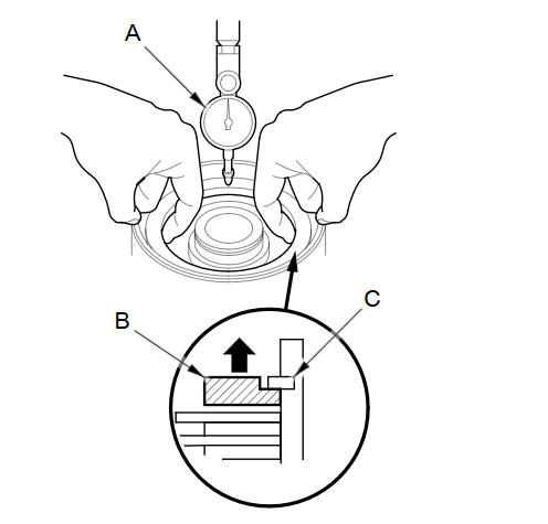
Zero the dial indicator with the clutch end-plate lifted up to the snap ring (C).
Release the clutch end-plate to lower it, then put the clutch compressor attachment on the end-plate (A).
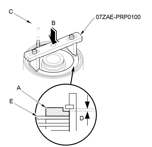
For the 1st, 3rd, and 5th clutches:
Press the clutch compressor attachment down with 150пјЌ160 N (15пјЌ16 kgf, 33пјЌ35 lbf) (B) using a force gauge, and read the dial indicator (C). The dial indicator reads the clearance (D) between the clutch end-plate and top disc (E). Take measurements in at least three places, and use the average as the actual clearance.For 2nd and 4th clutches:
Press the clutch compressor attachment down with 39 N (4 kgf, 9 lbf) (B) using a force gauge, and read the dial indicator (C). The dial indicator reads the clearance (D) between the clutch end-plate and top disc (E). Take measurements in at least three places, and use the average as the actual clearance.Clearance between Clutch End-Plate and Top Disc
Service Limit
1st clutch:
1.62пјЌ1.82 mm (0.064пјЌ0.072 in)
2nd clutch:
0.5пјЌ0.7 mm (0.020пјЌ0.028 in)
3rd clutch:
0.73пјЌ0.93 mm (0.029пјЌ0.037 in)
4th clutch:
0.7пјЌ0.9 mm (0.028пјЌ0.035 in)
5th clutch:
0.73пјЌ0.93 mm (0.029пјЌ0.037 in)
If the clearance of the 1st, 3rd, or 5th clutch is out of the service limit, select a new clutch end-plate from the following table.
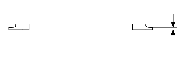
If the clearance of the 2nd or 4th clutch is out of the service limit, remove the clutch end-plate and check the clutch end-plate mark. Select a new clutch end-plate from the following tables by the mark on the old clutch end-plate. Use the AC-AL Plates table when the old clutch end-plate is marked with between AC and AL. Use the AM-AV Plates table when the old clutch end-plate is marked with between AM and AV.
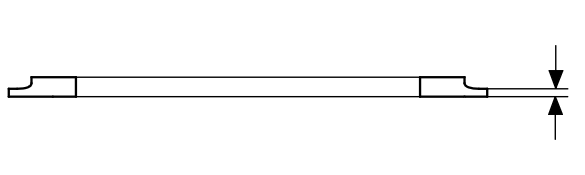
Install the new clutch end-plate, and recheck the clearance. If the thickest clutch end-plate is installed but the clearance is still over the service limit, replace the clutch discs and plates.
Test yourself
A quick Honda Fit quiz: every answer comes with an explanation and a link to the manual page.