Body Electrical System
Repair Procedures
In this manual: Body Electrical System
23steps
~138min
4/5difficulty
Done 0 of 23
Inspection
|

- Remove the front door trim panel. (Refer to Body - "Front Door Trim")
- Remove the front door module. (Refer to Body - "Front Door Module")
- Disconnect the actuator connectors.
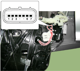
NO. Terminal Information Left Front Door Right Front Door 1 COM1 ADJUSTER 2 Central Motor Lock/Unlock 3 Door Lock COM2 4 Key Unlock X 5 COM2 X 6 Lock/Unlock Central Motor 7 ADJUSTER COM1 - Check actuator operation by connecting power and ground as shown below. To prevent damage to the actuator, apply battery voltage only momentarily.
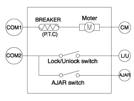
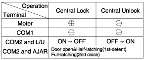
- Disconnect the power switch connector from the door lock actuator.
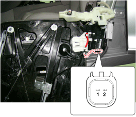
- Check continuity between the terminals in the half-latched state as shown below.
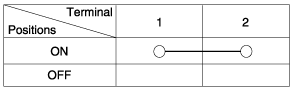
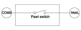
- If the power door latch fails to lock (automatic full lock), perform the rivet reset procedure. (1) The rivet reset procedure is completed by "Disconnect the power door fuse > Install the power door fuse > IGNITION ON".
Power Door Fuses Fuse Location Driver's Seat Front Intelligent Junction Box Passenger - Remove the rear door trim panel. (Refer to Body - "Rear Door Trim")
- Remove the rear door module. (Refer to Body - "Rear Door Module")
- Disconnect the actuator connectors.
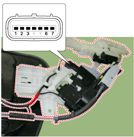
Power Door Fuses Fuse Location Driver's Seat Front Intelligent Junction Box Passenger
NO Terminal Information Rear Door (LH) Rear Door (RH) 1 COM1 ADJUSTER 2 Central Motor Lock/Unlock 3 X COM2 4 X X 5 COM2 X 6 Lock/Unlock Central Motor 7 ADJUSTER COM1 - Check actuator operation by connecting power and ground as shown below. To prevent damage to the actuator, apply battery voltage only momentarily.
- Disconnect the power switch connector from the door lock actuator.
- Check continuity between the terminals in the half-latched state as shown below.
- If the power door latch fails to lock (automatic full lock), perform the rivet reset procedure. (1) The rivet reset procedure is completed by "Disconnect the power door fuse > Install the power door fuse > IGNITION ON".
Power Door Fuses Fuse Location Driver's Seat Front Intelligent Junction Box Passenger - Remove the rear door trim panel. (Refer to Body - "Trunk Lid Trim")
- Disconnect the 6P connector from the actuator.
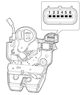
- Check actuator operation by connecting power and ground as shown below. To prevent damage to the actuator, apply battery voltage only momentarily.
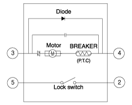
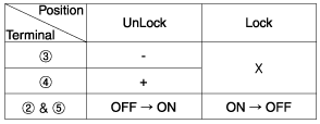
- Refer to the Power Trunk Module to inspect vehicles with the power trunk option.
- Disconnect the battery negative (-) terminal.
- Remove the rear reading lamp panel. (Body - "Trunk Lid Rear Panel")
- Remove the trunk lid trim. (Body - "Trunk Lid Trim")
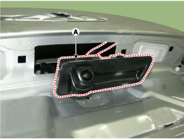
- Remove the luggage compartment opener switch assembly (A) after loosening the mounting clip.
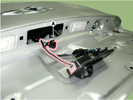
- Disconnect the connector and remove the trunk opener switch (A).
Test yourself
A quick Hyundai Genesis DH quiz: every answer comes with an explanation and a link to the manual page.
Was this page helpful?