Heating, Ventilation, and Air Conditioning
Temperature Control Actuator Repair Procedures
In this manual: Heating, Ventilation, and Air Conditioning
16steps
~96min
4/5difficulty
Done 0 of 16
Inspection
- Turn the ignition off.
- Disconnect the temperature control actuator connector.
- Make sure the temperature control actuator operates in the cool position when 12 V is applied to terminal 3 and ground terminal 7. Make sure the temperature control actuator operates in the warm position when the connection is reversed.
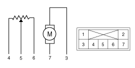
1. -
2. -
3. Cool Position
4. Warm Position5. Sensor (+5V)
6. Feedback Signal
7. Sensor Ground - Connect the temperature control actuator connector.
- Turn the ignition on.
- Check the voltage between terminals 5 and 6.Specification
Door Position Voltage (V) Fault Detection Max. Cool 0,5 ± 0,15 Low voltage: 0.1 V or less
High voltage: 4.9 V or moreMax. Heat 4,5 ± 0,15 - If the measured voltage does not meet the specification, check operation by replacing the existing temperature control actuator with a new genuine part. Then determine whether replacement of the temperature control actuator is required or not.
Diagnosis Using GDS
- The heating, ventilation, and air conditioning system faults can be quickly diagnosed using the Global Diagnostic System (GDS). ※ The GDS provides the following information: (1) Self-diagnosis: Check and display of diagnostic trouble codes (DTC). (2) Current data: Check the input/output status of system data. (3) Active test: Check the operating status of the system. (4) Additional functions: Other controls such as system option and zero point adjustment.
- Select "Vehicle Model" and the system to be checked to inspect the vehicle with the tester.
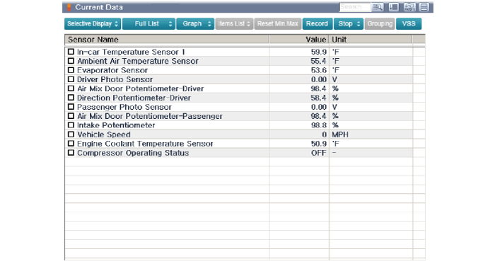
- Select the "Current Data" menu to check the current input/output data status. The input/output data for the sensors corresponding to the Temperature Control Actuator can be checked.
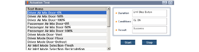
- To perform a forced operation on the temperature control actuator input factors, select "ACTUATOR TEST".
Replacement
- Disconnect the negative (-) battery terminal.
- Remove the glove box housing cover. (Refer to Body - "Glove Box Housing Cover")
- Remove the passenger side side defroster duct (A) after loosening the mounting screw.
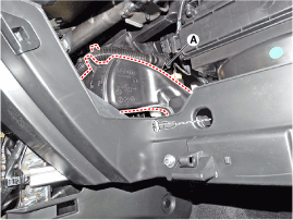
- Disconnect the connector (A) and remove the passenger side side panel after loosening the mounting screws, then remove the temperature control actuator (B).
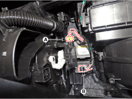
- To install, reverse the removal procedure.
Test yourself
A quick Hyundai Kona quiz: every answer comes with an explanation and a link to the manual page.
Was this page helpful?