Engine Mechanical System
Valve Clearance Adjustment
In this manual: Engine Mechanical System
6steps
~36min
2/5difficulty
Done 0 of 6
Valve Clearance Inspection and Adjustment
- Remove the cylinder head cover. (Refer to Cylinder Head Assembly - Cylinder Head Cover)
- Set the No. 1 cylinder to TDC/compression.
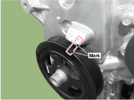
- Turn the crankshaft pulley and align its groove with the valve timing mark on the timing chain cover.
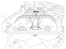
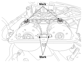
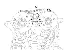
- Make sure the marks on the intake and exhaust CVVT sprockets are in a straight line on the cylinder head surface, as shown in the illustration. If not, turn the crankshaft one revolution (360°).
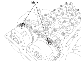
- Mark the timing chain links to match the timing marks on the CVVT sprockets with indelible marker.
- Turn the crankshaft pulley and align its groove with the valve timing mark on the timing chain cover.
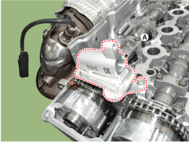
- Remove the exhaust oil control valve (OCV) adapter (A).
- Inspect the valve clearance.
- Check only the intake valves (for cylinders 1 and 2) and exhaust valves (for cylinders 1 and 3) for their clearance.
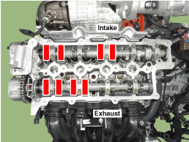
- Using a thickness gauge, measure the clearance between the lash adjuster and the camshaft base circle.
- Record the valve clearance measurements that are out of specification. They will be used later to determine the required lash adjuster for adjustment.
- Turn the crankshaft pulley one revolution clockwise (360°) and align its groove with the alignment mark on the timing chain cover.
- Check the intake valves (for cylinders 3 and 4) and exhaust valves (for cylinders 2 and 4) for their clearance.
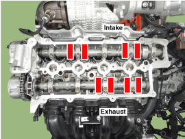
- Check only the intake valves (for cylinders 1 and 2) and exhaust valves (for cylinders 1 and 3) for their clearance.
- Remove the engine mount support bracket.
- Place a jack under the oil pan.
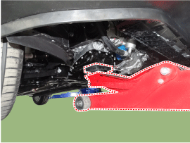
- Disconnect the engine ground cable (A).
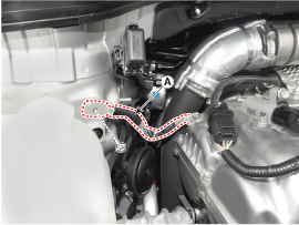
- Remove the engine mounting bracket. (Refer to Engine and Transaxle Assembly - "Engine Mounting")
- Slightly raise the engine with the jack to create clearance.
- Place a jack under the oil pan.
- Adjust the intake and exhaust valve clearance.
- Remove the service hole bolt (A).
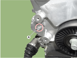
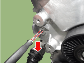
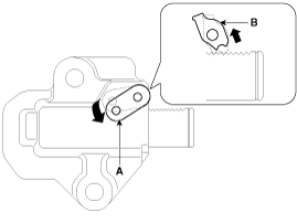
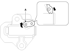
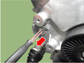
- Lock the timing chain tensioner in the fully retracted position. Insert a pick tool into the service hole in the timing chain cover and lift the ratchet plate (A) on the left side of the tensioner so that the pawl (B, located inside the tensioner behind the ratchet plate) is raised.
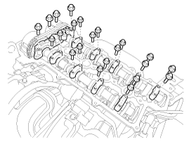
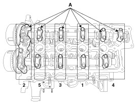
- Remove the camshaft bearing caps (A) in the order shown below.
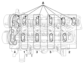
- With the pawl raised, ask an assistant to lift the exhaust CVVT and camshaft (A) to allow the tensioner plunger (B) to retract.
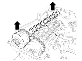
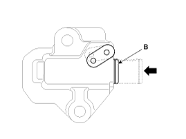
- When the tensioner plunger is fully retracted, lift the ratchet plate (A) on the left side again through the service hole in the chain cover to align the hole in the ratchet plate with the hole in the tensioner body behind the ratchet plate, then lock the tensioner by inserting a pick tool through the holes of the ratchet plate and tensioner body.
- Separate the exhaust camshaft (A) from the exhaust CVVT by removing the bolt.
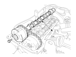
- Remove the exhaust CVVT (A) from the timing chain.
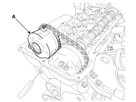
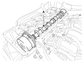
- Remove the intake CVVT and camshaft (A).
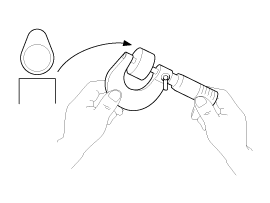
- Measure the thickness of the removed tappet using a micrometer.
- Calculate the thickness of the new tappet so that the valve clearance is within the specified value. Valve clearance (engine coolant temperature: 20 °C) T: Thickness of removed tappet. A: Measured valve clearance. N: Thickness of new tappet. Intake: N = T + [A - 0.20 mm (0.0079 in.)] Exhaust: N = T + [A - 0.25 mm (0.0098 in.)]
- Select a new tappet with a thickness as close as possible to the calculated value.
- Install the new tappet into the cylinder head.
- Install the intake CVVT and camshaft (A) with the alignment mark on the intake CVVT sprocket aligned with the mark (painted link) on the timing chain.
- Install the exhaust CVVT (A) with the alignment mark on the exhaust valve. Align the CVVT sprocket with the mark (painted link) on the timing chain.
- Install the exhaust camshaft (A) onto the exhaust CVVT.
Tightening torque: 63.7–74 N·m
- Remove the pick tool from the service hole in the timing chain cover.
- Make sure that each alignment mark on the intake and exhaust CVVT sprockets is aligned, as shown in the illustration.
- Install the service bolt (A).
Tightening torque: 27.5 - 30 N·m
- Install the engine mount bracket. (Refer to Engine and Transaxle Assembly - "Engine Mounting")
- Connect the engine ground cable (A).
Tightening torque: 10.8 - 13.7 N·m
- Remove the jack from the oil pan.
- Connect the engine ground cable (A).
- Install the camshaft bearing caps (A) in the order shown below. Tightening torque Step 1 M6 bolt: 5.9 N·m M8 bolt: 9.8 N·m Step 2 M6 bolts: 11.8 - 12.7 N·m M8 bolts: 18.6 - 23 N·m
- Rotate the crankshaft two revolutions in the normal direction of rotation (clockwise) and make sure that the alignment marks on the intake and exhaust CVVT sprockets are in a straight line on the cylinder head surface.
- Recheck the valve clearance. Valve clearance (engine coolant temperature: 20 °C) [Specification] Intake: 0.17 - 0.23 mm (0.0067 - 0.0091 in.) Exhaust: 0.32 - 0.38 mm (0.0126 - 0.0150 in.)
- Install the exhaust oil control valve (OCV) adapter (A).
Tightening Torque: 9.8–11.8 N·m
- Install the cylinder head cover. (Refer to Cylinder Head Assembly - "Cylinder Head Cover")
- Remove the service hole bolt (A).
Test yourself
A quick Hyundai Kona quiz: every answer comes with an explanation and a link to the manual page.
Was this page helpful?