Body Electrical System
Smart Key
In this manual: Body Electrical System
46steps
~276min
4/5difficulty
Done 0 of 46
Components and Component Location
COMPONENTS

| No. | CONNECTOR A | CONNECTOR B | C-CONNECTOR |
| 1 | BATT (+) | ALL2 Relay Output | Immobilizer Antenna Power |
| 2 | BATT (+) | ALL1 Relay Output | Wheel Speed Sensor Input |
| 3 | Internal Antenna 1_GND | - | SSB1 Switch Signal_Input |
| 4 | Bumper Antenna GND | - | - |
| 5 | Internal Antenna 2_GND | ESCL Communication | ESCL Unlock Switch |
| 6 | Auxiliary Door Antenna_GND | EMS Communication | Input Signal "P" |
| 7 | - | B-CAN (High) | Brake Switch Input |
| 8 | Driver Door Antenna Ground | B-CAN (Low) | IGN2 signal_input |
| 9 | - | - | IGN1 Signal_Input |
| 10 | SSB Illumination (-) | - | Starter Relay Output |
| 11 | Exterior Buzzer | - | Immobilizer Antenna GND |
| 12 | ESCL Power Supply | ACC Relay Output | RPM_Input |
| 13 | - | - | SSB2 Switch Signal_Input |
| 14 | Interior Antenna 1 Power | MASS | Driver Door Switch Signal_Input |
| 15 | Bumper Antenna Power | KEY OUT Indicator | Passenger Door Switch Signal Input |
| 16 | Interior Antenna 2 Power | SSB LED (ACC) | Start Signal Feedback_Input |
| 17 | Auxiliary Door Antenna_Power | SSB LED (Ignition) | Stop Lamp Fuse signal_input |
| 18 | - | - | ACC signal_input |
| 19 | Driver Door Antenna Power | SSB LED (OFF) | - |
| 20 | - | SSB Illumination (-) | MASS |
| 21 | ESCL Activation | Immobilizer Indicator | |
| 22 | ESCL GND | - |
Circuit Diagrams
Wiring Diagram

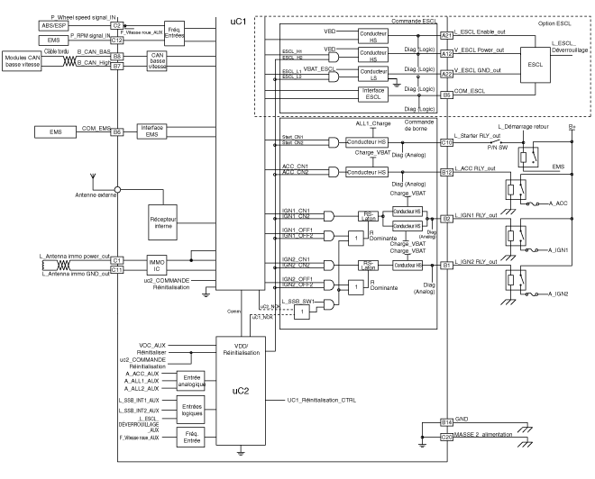
Repair Procedures
DEPOSIT
Smart Key- Disconnect the negative (-) battery terminal.
- Remove the lower airbag panel. (Refer to Body - "Lower Instrument Panel")
- Disconnect the antenna cable (A) and connectors from the SMK unit (B).

- Remove the SMK unit (A) after loosening the mounting screws.
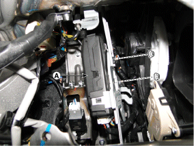
- Disconnect the negative (-) battery terminal.
- Remove the front floor console tray. (Refer to Body group - Floor Console)
- Remove Interior Antenna 1 (B) by unscrewing the mounting nuts, and disconnect the connector (A).
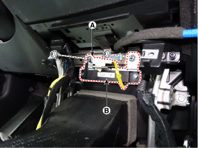
- Disconnect the negative (-) battery terminal.
- Remove the rear floor carpet. (Refer to Body - "Carpets")
- Remove the room antenna 2 (B) by unscrewing the mounting nuts, and disconnect the connector (A).

- Disconnect the negative (-) battery terminal.
- Remove the rear bumper cover. (Refer to Body - Rear Bumper Cover)
- Remove the rear bumper antenna (A) by loosening the mounting screws.

- Disconnect the negative (-) battery terminal.
- Remove the guide from the front left wheel. (Refer to Body - "Front Fender")
- Remove the buzzer (A) after disconnecting the connector.

- Disconnect the negative (-) battery terminal.
- Remove the front door outside handle. (Refer to Body - Front Door Outside Handle)
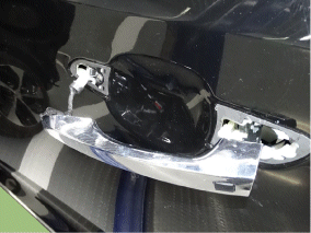
- Disconnect the negative (-) battery terminal.
- Remove the rear door trim panel. (Refer to Body - "Rear Door Trim")
- Remove the rear panel of the rear door. (Refer to Body - "Rear Door Rear Panel")
- Remove the luggage compartment door opener switch (A) after loosening the mounting screws.

Inspection
Smart Key (See Smart Key System - Smart Key Diagnosis), Smart Key Switch (See Smart Key System - Smart Key Diagnosis), ANTENNA (See Smart Key System - Smart Key Diagnosis), Outside Door Handle- Disconnect the front door outside handle connector (A).
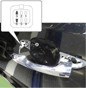
- Check the continuity of the circuit between terminals No. 3 and No. 6.

NO Description 1 Door Antenna (-) 2 Flashlight LED (-) 3 Door Lock/Unlock Button 4 Door Antenna (-) 5 Flashlight LED (-) 6 Door lock/unlock button switch ground

- Check the continuity of the circuit between the terminals of the luggage compartment door lock.

- If continuity is not specified, inspect the switch.

REMEDY
Smart Key- Install the smart key unit.
- Install the Smart Key unit mounting bolts and connect the connector.
- Install the glove box.
- Connect the negative (-) battery terminal and check the Smart Key system.
- Install the room antenna 1.
- Install the front console tray onto the floor.
- Connect the negative (-) battery terminal and check the Smart Key system.
- Install the room antenna 2.
- Install the rear mat.
- Connect the negative (-) battery terminal and check the Smart Key system.
- Install the rear bumper antenna.
- Install the rear bumper cover.
- Connect the negative (-) battery terminal and check the Smart Key system.
- Install the outside handle.
- Install the front door outside handle.
- Connect the negative (-) battery terminal and check the Smart Key system.
- Install the luggage compartment door opener switch.
- Install the rear door trim panel.
- Install the rear panel of the rear door.
- Connect the negative (-) battery terminal and check the Smart Key system.
Test yourself
A quick Hyundai Tucson quiz: every answer comes with an explanation and a link to the manual page.
Was this page helpful?