Body Electrical System
Description and Operation
In this manual: Body Electrical System
~6min read
Description
System Overview. The system provides the following functions:- Human-machine interface using a single-stage button to switch terminals and start the engine.
- Control of external relays to switch the ACC / IGN1 / IGN2 and STARTER terminals without using a mechanical ignition switch.
- Vehicle status indication by LEDs or text messages on the display.
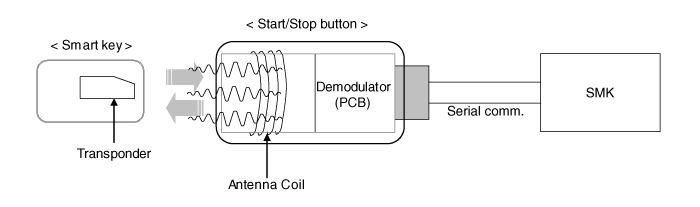
- Immobilizer function by LF transponder communication between the key fob and the key fob holder.
- Redundant architecture for high system reliability.
- Interface with the vehicle Low Speed CAN communication network.
- Interface with the vehicle LIN communication network, depending on platform.
- Switching of ACC/IGN1/IGN2 terminals.
- Control of the STARTER relay BAT line (high side) based on communication with the EMS ECU.
- Control of the immobilizer function.
- Control of the BES warning function.
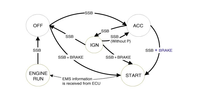
- Controls ignition and engine on/off by sending a signal to the IPM and PDM.
- Status indication by the ON/OFF LED lamp (amber or green).
| No. | Indicator lamp | Conditions |
| 1 | Indicator lamp is on | Door open, tail lamp on, ACC, IG on |
| 2 | Indicator lamp on for 30 sec. > lamp off | Door closed, tail lamp off, ignition off |
| 3 | Indicator lamp off | Remote LOCK, passive LOCK |
| 4 | Tail lamp dimmer rheostat (illumination lamp) | |
Indicator ON/OFF Status According to Ignition Switch Position
| No. | Ignition conditions | Start button indicator status |
| 1 | IG OFF | LED is off |
| 2 | IG ACC | LED is yellow |
| 3 | IGNITION ON (engine off) | Green LED is on |
| 4 | Cranking | Maintain LED status before start |
| 5 | Engine is running | LED is off |
- RKE without PEPS
- SMART KEY FOB
- "Start-stop button (SSB) monitoring",
- "Immobilizer communication" (with the engine control unit for immobilizer unlocking),
- "Authentication server" (transponder validity and, in the case of the Smart Key option, Passive Fob authentication),
- "System consistency check",
- "System diagnostics",
- Control of message display / warning buzzer.
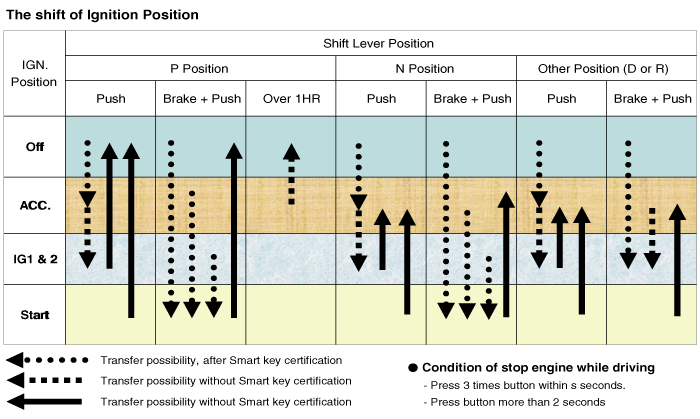
- To activate the OFF, ACC, IGN and START power modes, switch the corresponding terminals.
- To start the engine
- To stop the engine
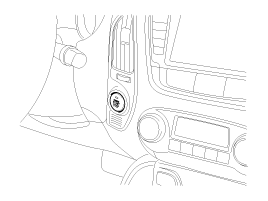
| System Status | Terminal status | Engine Status |
| 1. OFF — locked | OFF | Stopped |
| 2. OFF — unlocked | OFF | Stopped |
| 3. ACC | ACC | Stopped |
| 4. IGN | IGN1, IGN2, ACC | Stopped |
| 5. START | IGN1, START | Cranking |
| 6. IGNITION - Engine | IGN1, IGN2, ACC | Run |
| (stands for "Self-Contained") |
Regarding terminals, the system states described in the table above are the same as in a system based on a mechanical ignition lock. One difference from a mechanical ignition switch-based system is that the BES system allows a special transition from [OFF] to [START] without passing through the [ACC] and [IGN] states. SYSTEM STATES IN VIRGIN MODE. The BES system can be set to 5 different states (OFF, LOCK, unavailable in virgin mode), depending on the terminal status and engine status:
| System Status | Terminal status | Engine Status |
| 1. OFF - UNLOCKED | OFF | Stopped |
| 2. ACC | ACC | Stopped |
| 3. IGN | IGN1, IGN2, ACC | Stopped |
| 4. Start | IGN1, START with special activation pattern, refer to chapter 6.2.1 for details. | Cranking |
| 5. IGNITION - Engine | IGN1, IGN2, ACC | Run |
| (stands for "Self-Contained") |
Regarding terminals, the system states described in the table above are the same as in a system based on a mechanical ignition lock. The difference from a mechanical ignition switch-based system is that the BES system allows a specific transition from [OFF] to [START] without passing through [ACC] and [IGN].
Test yourself
A quick Hyundai Tucson LM quiz: every answer comes with an explanation and a link to the manual page.
Was this page helpful?