Body Electrical System
Smart Key Unit Components and Component Location
In this manual: Body Electrical System
~1min read
Component (1)
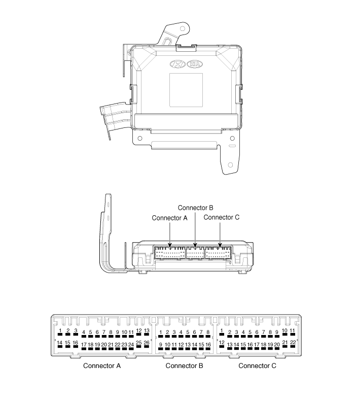
| No. | Connector A (26-pin) | Connector B (16-Pin) | Connector C (22-Pin) |
| 1 | VBAT Load | C CAN Low | SSB Illumination Ground |
| 2 | - | C CAN High | - |
| 3 | Power Ground 1 | - | SSB Indicator OFF |
| 4 | IGN 1 | - | Interior Antenna No. 2 Power |
| 5 | IGN1 Relay | Brake Switch | Interior Antenna No. 1 Power |
| 6 | ACC | Immobilizer Antenna Power | - |
| 7 | IGN 2 | - | - |
| 8 | SSB Switch 2 | Wheel Speed | Mainline Antenna Power |
| 9 | - | Driver Switch | Bumper Antenna Power |
| 10 | RF COM | - | Auxiliary Side Antenna |
| 11 | - | - | Driver Side Antenna Power |
| 12 | B CAN High | P Position / Clutch Switch | SSB Ignition LED |
| 13 | B CAN Low | Start Recall | SSB Illumination Power |
| 14 | CPU VBAT | Immobilizer Antenna Ground | - |
| 15 | - | - | Interior Antenna No. 2 Ground |
| 16 | Power Ground 2 | SSB ACC LED | Interior Antenna No. 1 Ground |
| 17 | Starter Relay | - | |
| 18 | IGN2 Relay | - | |
| 19 | ACC Relay | Main Antenna Ground | |
| 20 | - | Bumper Antenna Ground | |
| 21 | - | Auxiliary Side Antenna Ground | |
| 22 | - | Driver Side Antenna Ground | |
| 23 | RPM | ||
| 24 | EMS COM | ||
| 25 | SSB Switch 1 | ||
| 26 | Assist Switch Button |
Component (2)
Test yourself
A quick Kia Cadenza VG Owner's Manual quiz: every answer comes with an explanation and a link to the manual page.
Was this page helpful?