Auto Defogging Actuator Repair procedures
Inspection
Switch "OFF" the ignition.
Disconnect the auto defogging sensor connector.
Connect the power (+) terminal to mode actuator connector terminal 3, and ground the negative (-) terminal to terminal 7. Then, inspect that the motor is operated in defrost mode. Reverse the connections to see that it operates in reverse.
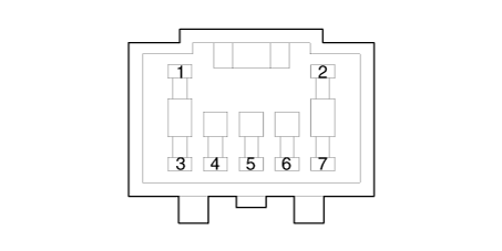
1. -
2. -
3. DEF (Open)
4. Sensor Ref (+5V)5. Actuator Feed back
6. Sensor Ground
7. DEF (Close)Connect the auto defogging actuator sensor connector.
Switch "ON" the ignition.
Check the voltage between terminals 4 and 5.
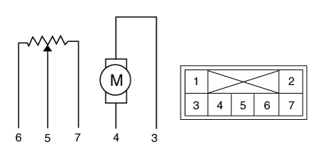
1. -
2. -
3. OPEN (CW)
4. SENSOR REF (+5V)5. Actuator Feed back
6. Sensor Ground
7. Close (CCW)
Specification
Door position Voltage (V) Error detect DEF (ON) 1.7 ± 0.15V Low voltage : 0.6V or less DEF (OFF) 4.7 ± 0.15V High voltage : 4.7V or more
It will feedback the current position of the actuator to controls.
If the measured voltage does not satisfy the specifications, replace with a genuine auto defogging actuator.
Replace the auto defogging actuator if it is proved that there is a problem with it.
Replacement
Disconnect the negative (-) battery terminal.
Remove the glove box housing.
(Refer to Body - "Glove Box Housing".)
Loosen the mounting screw and remove the passenger seat shower duct (A).
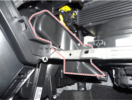
Disconnect the connector and then remove the auto defogging actuator (A) after loosening the screws.

Install in the reverse order of removal.