Battery Pack Assembly Repair procedures
Removal
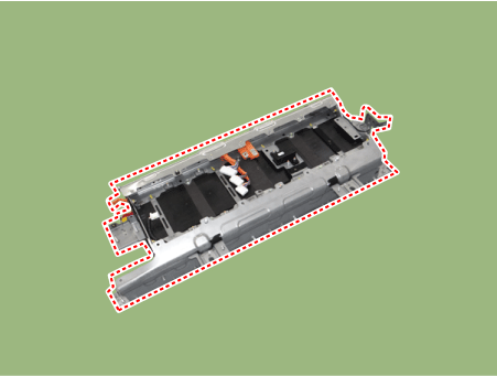
Remove the high voltage battery system assembly.
(Refer to High Voltage Battery System - "Removal")
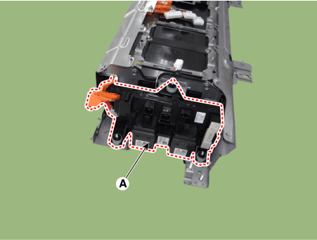
Remove the BMS ECU after loosening the mounting nuts.
BMS ECU mounting nut : 7.8 - 11,8 N·m
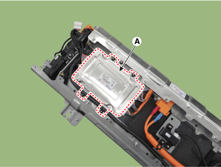
Remove the safety plug cable (A) after loosening the mounting bolts and nut.
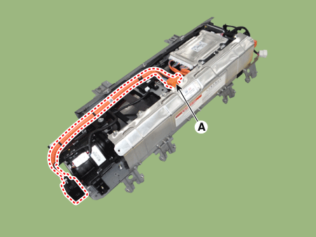
Remove the cooling fan (A) after loosening the mounting bolt and nuts.

Remove the BMS ECU extension wiring harness (A).
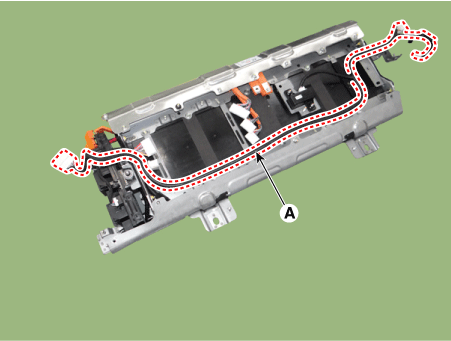
Remove the power relay assembly (A) after loosening the mounting nuts.
Power relay assembly mounting nut :
7.8 - 11,8 N·m
Installation
Install the high voltage battery pack assembly in the reverse order of removal.
Inspection
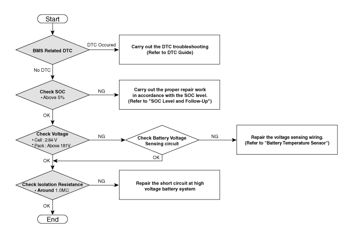
[Battery Pack Assembly Troubleshooting Chart]
[SOC Level and Follow-up]
| SOC | Symptom | Warning Lamp | Follow-up | ||
| MIL | Service | Fuel | |||
|
- | - | - | ||
| 10 ~ 15% |
|
- | - | ON |
|
| ON | - | - |
|
||
| ON | ON | - | |||
| - | ON | - | |||
| On | ON | ON | |||
| 5 ~ 10% |
|
- | - | ON |
|
| ON | - | - |
|
||
| ON | ON | - | |||
| - | ON | - | |||
| ON | ON | ON | |||
| 0 ~5% |
|
ON | - | - |
|
| ON | ON | - | |||
| - | ON | - | |||
| ON | ON | ON | |||
| 0% 이하 | ON | - | - |
|
|
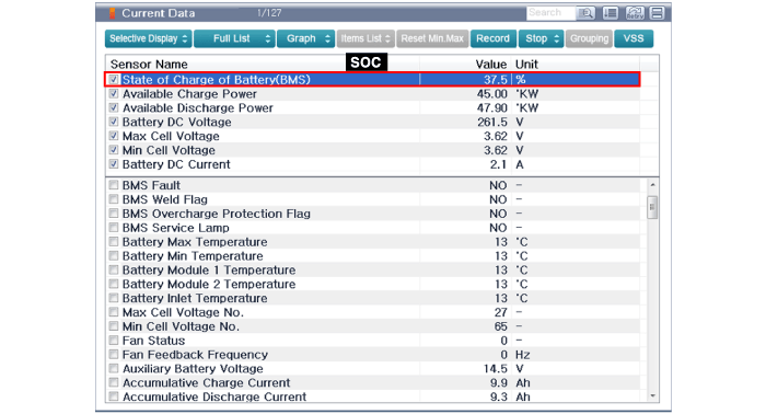
[SOC Inspection]
Connect the KDS/GDS to the Data Link Connector (DLC).
Turn the ignition switch ON.
Check the SOC in GDS service data.
SOC: Above 5 %
[Battery Voltage Inspection]
Connect the KDS/GDS to the Data Link Connector (DLC).
Turn the ignition switch ON.
Check the cell and pack voltage in GDS service data.
Cell Voltage: Above 2.84 V Pack Voltage: Above 181 V


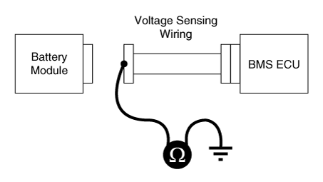
[Voltage Sensing Circuit Inspection]
Shut off the high voltage circuit (Refer to "High Voltage Shutoff Precedure").
Remove the battery temperature sensor (Refer to "Battery Temperature Sensor").
Check the continuity of the wiring between the harness connectors of the module and BMS ECU.
Specification : below 1Ω

Connect the harness connectors to the BMS ECU.
For checking the short circuit to ground, measure resistance between the module harness connectors and chassis ground.
Specification : 1MΩ or higher
[Isolation Resistance Inspection]
Connect the KDS/GDS to the Data Link Connector (DLC).
Turn the ignition switch ON.
Check the isolation resistance in KDS/GDS service data.
Isolation Resistance: Around 1.0 MΩ
