Engine And Transaxle Assembly Repair procedures
Removal
Shut off the high voltage circuit.
(Refer to Engine Mechanical System - “High Voltage Shut off Procedure”)
Remove the engine cover.
(Refer to Engine and Transaxle Assembly - "Engine cover")
Remove the air cleaner assembly.
(Refer to Intake and Exhaust System - "Air Cleaner")
Remove the engine room under cover.
(Refer to Engine and Transaxle Assembly - "Engine Room Under cover")
Drain the engine coolant.
(Refer to Cooling System - "Coolant")
Drain the inverter coolant.
(Refer to Hybrid Motor System - "Coolant")
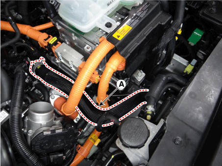
Disconnect the radiator upper hose (A).
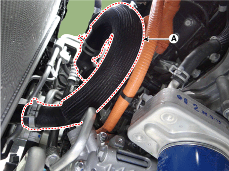
Disconnect the radiator lower hose (A).
Remove the hybrid power control unit (HPCU) and tray.
(Refer to Hybrid Control System - "Hybrid Power Control Unit (HPCU)")
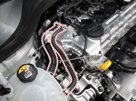
Disconnect the reservoir tank coolant hose (A).
Disconnect the hybrid starter generator (HSG) water hose (A).
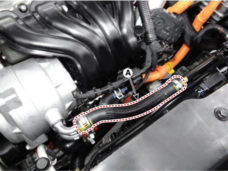
Disconnect the electric water pump (EWP) coolant hose (A).

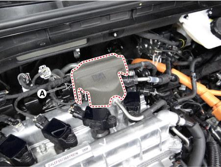
Remove the high pressure fuel pump foam (A).
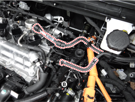
Disconnect the fuel hose (A) and purge control solenoid valve (PCSV) hose (B).
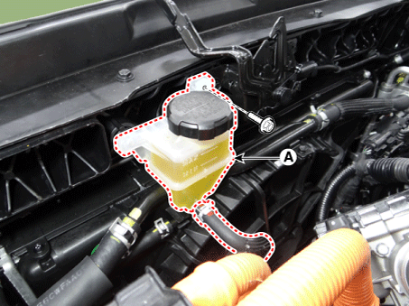
Separate the clutch reservoir tank (A).
Tightening torque : 3.9 - 5,9 N·m
Remove the engine wiring.
Disconnect the ground cable (A).
Tightening torque : 10.8 - 13,7 N·m
Disconnect the fuse box main wiring connector (B).
Pull the main wiring protector (C) upward to remove it from engine room.
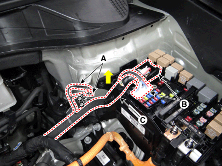
Disconnect the heater hose (A).
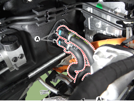
Remove the front muffler.
(Refer to Intake and Exhaust System - "Muffler")
Disconnect the wire harness connectors, control cables from the dual clutch transmission.
(Refer to DCT(Dual Clutch Transmission) System - "DCT(Dual Clutch Transmission")
Remove the roll rod bracket (A).
Tightening torque
Bolt (B) :
107.9 - 128 N·m
Bolts (C) :
49.0 - 64 N·m

Remove the roll rod mounting support bracket (A).
Tightening torque : 49.0 - 69 N·m
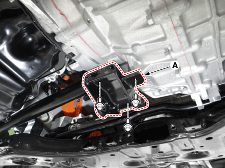
Remove the sub frame.
(Refer to Suspension system - "Sub frame")
Support the engine and transaxle assembly on a lift table.
Disconnect the ground cable (A).
Tightening torque : 10.8 - 13,7 N·m

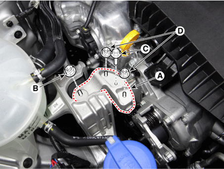
Remove the engine mounting support bracket (A).
Tightening torque
Nut (B) :
88.3 - 108 N·m
Bolt (C) and nuts (D) :
58.8 - 74 N·m
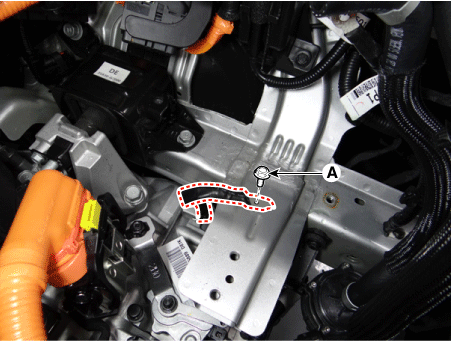
Remove the dual clutch transmission ground cable mounting bolt (A).
Tightening torque : 10.8 - 13,7 N·m
Remove the transaxle mounting side panel packing (A).

Remove the transaxle mounting bolts (A).
Tightening torque : 88.3 - 108 N·m
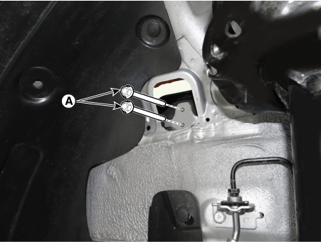
Remove the engine and transaxle assembly by lifting vehicle.

Installation
Install in the reverse order of removal.
Add all the necessary fluids and check for leaks. Connect KDS/GDS. Check for codes, note, and clear. Recheck.