Body Electrical System
Instrument Cluster Components and components location
In this manual: Body Electrical System
~1min read
Components
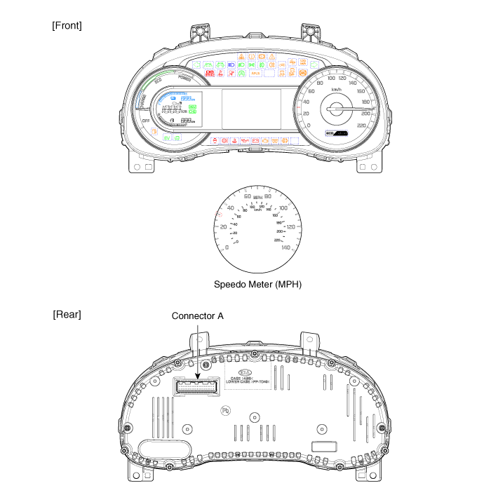
[Standard Type ("3.5")]
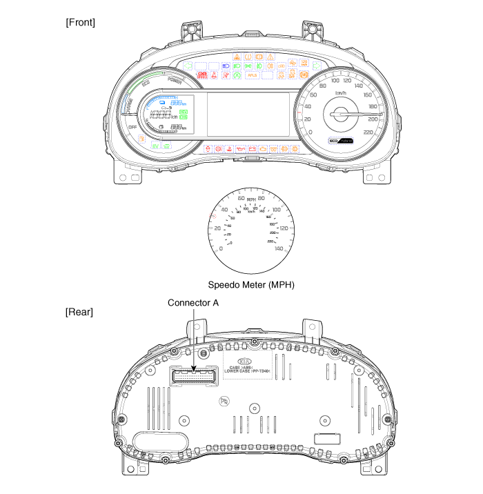
[Super Vision Type ("4.3")]
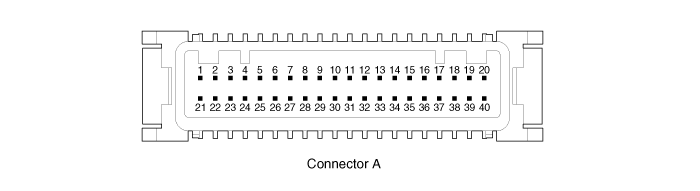
Connector Pin Information
| No. | Description | No. | Description |
| 1 | Ground | 21 | Trip switch (-) |
| 2 | Illumination (-) | 22 | Trip switch 1 (+) |
| 3 | Rheostat switch (Down)_Input | 23 | Trip switch 2 (+) |
| 4 | Rheostat switch (Up)_Input | 24 | AT ('P' Position) |
| 5 | - | 25 | AT ('R' Position) |
| 6 | Oil press switch_Input | 26 | AT ('N' Position) |
| 7 | Washer level low_Input | 27 | AT ('D' Position) |
| 8 | Alternator_Input | 28 | AT ('S' Position) |
| 9 | - | 29 | Multimedia-CAN (Low) |
| 10 | Driver mode switch_Input | 30 | Multimedia-CAN (High) |
| 11 | Dentent | 31 | Active ECO switch_Input |
| 12 | - | 32 | Chassis-CAN (High) |
| 13 | - | 33 | Chassis-CAN (Low) |
| 14 | Fuel sender (+)_Input | 34 | Cluster speaker (+) |
| 15 | - | 35 | Cluster speaker (-) |
| 16 | Fuel sender (-)_Input | 36 | - |
| 17 | Immobilizer_Input | 37 | Ground |
| 18 | Vehicle speed_Output | 38 | IGN3 (PHEV Only) |
| 19 | Air bag (+)_Input | 39 | IGN 1 |
| 20 | Tail lamp_Input | 40 | Battery (+) |
Was this page helpful?